If you’re worried about the safety of your circuit and want to implement some basic protection on your MOSFETs from short circuits or overloads, read through this article.
Introduction
A MOSFET is a semiconductor device that can drive large loads through its gate terminal. As you drive higher power peripherals, the more you need to implement robust protection mechanisms both for your circuit and load. This will prevent catastrophic fires and your circuit from getting damaged.
Since you control the gate drive to turn on your MOSFET to deliver power to its load, you should be able to predict when this happens and what amount of power it can deliver to its load. With these data, you’ll be able to generate a control mechanism in the form of a circuit and write firmware so that you can reliably time this event.
Once you’ve successfully protected your circuit and load, you’ll be more confident about deploying your boards in the field. The next part will discuss the basic operation of a MOSFET to help you understand how to protect it effectively.
How MOSFETs Work
MOSFET stands for Metal-Oxide-Semiconductor Field Effect Transistor. As its name implies, it works by controlling an electric field through its Gate terminal so that you can control the current flow between its Drain and Source. There are 2-different types of MOSFETs, namely N-Channel and P-Channel types illustrated below:
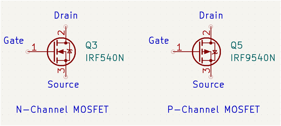
Using a MOSFET has several advantages over other kinds of semiconductor driver devices. First, its control terminal (the gate) works with a very small amount of current. This property makes the MOSFET feasible to use with microcontrollers with a limited output drive. Next, it’s primarily a voltage-controlled device. This means that if you’re dealing with digital logic, you’ll only be concerned with overcoming its turn-on (VGS) threshold voltage. You don’t need to worry about its gate current drive characteristics, unlike the ones being employed on the base terminal of a BJT.
| MOSFET | BJT |
|---|---|
| Voltage Driven | Current Driven |
| Very Low Gate current | Base current calculation is required for proper device operation |
| VGS threshold voltage is required to turn the device ON | VBE threshold voltage is required to turn the device ON |
With these properties, we can formulate a simple way to protect a MOSFET from shorts or overloads using only basic of shelf components. This will be discussed in the next part.
How to Protect a MOSFET using a BJT
Consider an N channel type MOSFET that turns ON when a positive voltage of 5V is applied to its gate terminal.
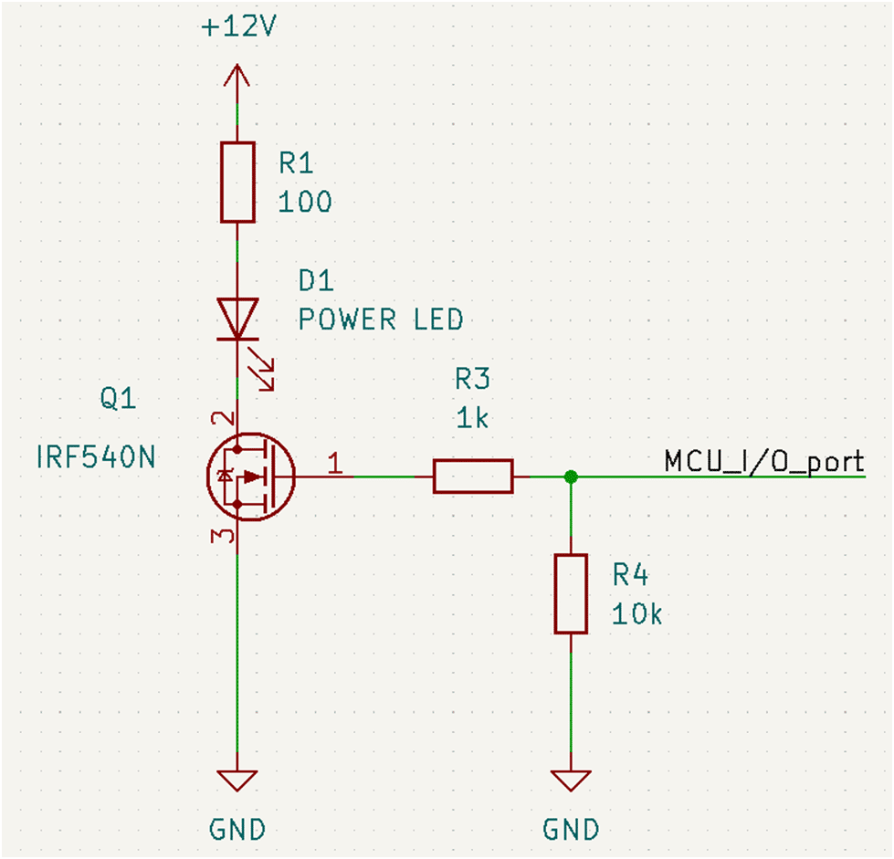
Here we have a MOSFET Q1 that drives a power LED D1. The resistor R3 here is just used to compensate for the internal parasitic capacitance of the MOSFET in case we do switching of the gate to higher frequencies. R4 is used as a pull-down in case the MCU_I/O_port line goes into high impedance.
Let’s now implement a short circuit or overload protection for this circuit by adding a low-power BJT Q2, a sense resistor R2, and an OP-AMP circuit.
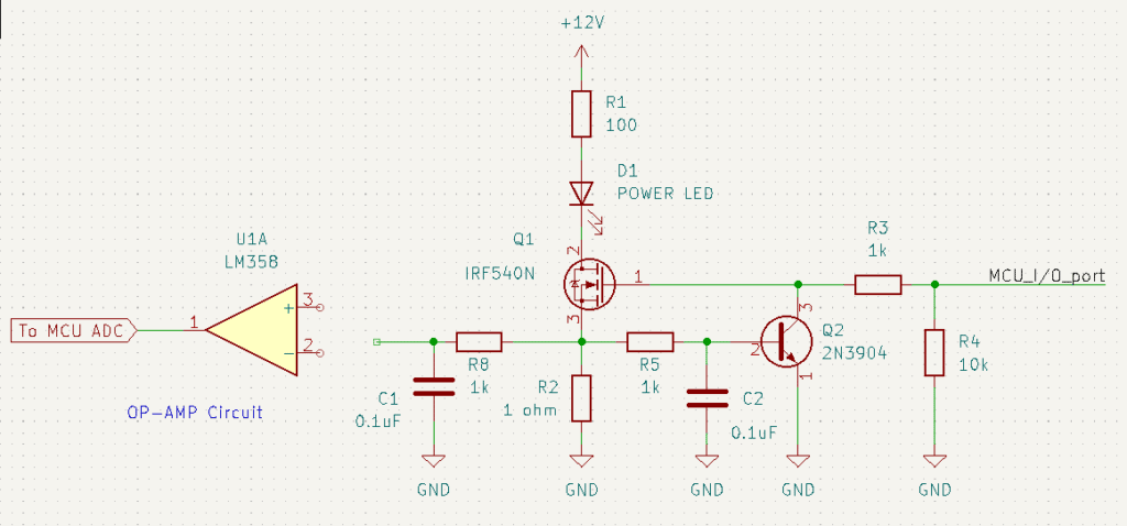
This current sense resistor will have a voltage drop proportional to the current of the load and the drain-source terminals. Choose this resistor’s value in such a way that it will generate a sufficient voltage drop to turn on the VBE of the BJT when your overload current occurs. When this happens, your BJT will compensate and pull down the MOSFET’s gate voltage in such a way that the circuit produces the load current only up to the overload condition.
Note, however, that you’ll need a MOSFET that can handle the power requirements of this overload condition. Consider shorting out the load entirely. You’ll see that most of the voltage drop of your power supply is across your MOSFET (subtracting only a small voltage drop on your sense resistor). Multiplying this voltage drop with the overload current presents your MOSFET’s power dissipation. At this time, you should plan a way to turn off your MOSFET if it can’t handle this overload condition indefinitely (except if you decide to place a limiting resistor in series with your load) so that it will not get destroyed. This situation will be discussed in the next part.
Creating Firmware To Get Out Of The Overload Condition
Theoretically, by using an OP-AMP combined with the ADC of your MCU, you should be able to detect this overload condition and then do something about it. The best thing to do is turn off the MOSFET by setting its gate voltage to low and then latch this condition. Inform the user that an overload or short-circuit occurred by lighting up a LED so that he can remove this condition. Next, instruct him to override this latch event by pressing a button or resetting the MCU. An advantage of this circuit (compared to a simple BJT protection circuit) is that you can inform the user that your load is nearing the threshold limit even before the overload happens. You can even display the current value. You have this feature because of the OP-AMP ADC combination.
Because the sense resistor only outputs small voltages, the OP-AMP circuit was added. Additionally, some low-pass filtering components, R5, C2, R8, and C1 were also added. This will prevent false alarms that can trigger the overload protection mechanism of your circuit. Employ external filtering techniques and/or do this with code. It’s a good idea to oversample your data to eliminate noise that can execute false triggers.
Conclusion
We’ve discussed basic MOSFET characteristics and how to protect their output from short circuits and overloads. We’ve also included how to detect and latch an overload condition using an OP-AMP and your MCU’s ADC.
A simpler way to protect your MOSFETs without using an ADC can be found in Easy MOSFET Protection from Short Circuits & Overloads.