Introduction
Sensors are often used to gather data that are acquired from a physical environment. After that, these data can be transferred to a table or graph that represents a certain behavior in relation to time. Data can be logged for many hours, months, or years depending on the planned data acquisition lifespan. Finally, information gathered from this data can be used to understand the environment in which it was used. Alternatively, training an AI/Machine Learning model can also be done based on this data.
Obtaining this data is relatively easy from network connected devices, or devices that already installed interfaces, such as USB ports, disk drives etc like you would find on a computer. But what if you need to get this information off an arduino device that is not connected to any network or has the storage capacity to store this data? This is where a storage solution is required. In this post, we will explore just that, adding a MicroSD card module to an Arduino device that will write to a SD Card for the purpose of capturing data to be viewed at a later date.

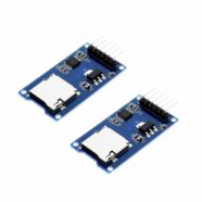
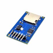
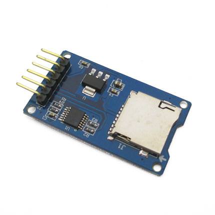
The MicroSD Card Module
A micro SD Card Module Shield is a tool for transferring data to and from a standard SD card and an Arduino board. The module is compatible with different kinds of Arduino boards as well as other microcontrollers. Ultimately, they will be used for storing digital data or data logging.
This module eliminates storage space limitations on Arduino and enables users to have variable memory sizes to store data.
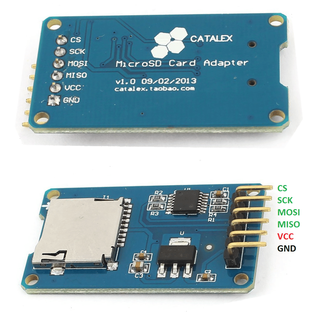
MicroSD Card Module Pin Out
| PIN | DESCRIPTION |
|---|---|
| MISO (Master Out, Slave In) | Pin where data is going from the master to the slave |
| MOSI (Master In, Slave Out) | Pin where data is going from the slave to the master |
| SCK (Serial Clock) | This is the clock pulse for both the master and slave to be able to sample data bits |
| SS (Slave Select) | Pin which tells a paticular slave to go "Active" and talk to the master. |
| VCC | 5V or 3.3V DC Power supply (A 3.3V voltage regulator steps down the voltage from 5V to 3.3V) |
| GND | Common Ground |
Introduction to SPI
In order to use the MicroSD Card Module, an SPI protocol is used.
SPI stands for “Serial Peripheral interface”. This protocol is used so that multiple devices can communicate with each other over a short distance at high speed.
There is one “master” device that initiates the communication and supplies the clock. This clock controls the data transfer rate. In SPI, there can be one or more slave devices. For a setup with more than one slave, each slave must have its own “slave select” signal.
SPI is the fastest serial protocol on the Atmega328 (and similar) chips. It has a clock rate of half of its crystal value. So you can get an 8MHz clock rate using a 16MHz crystal oscillator. I2C has lower clock speeds and can only go as high as 400kHz. Because of this, SPI is preferred over I2C when communicating at faster speeds.
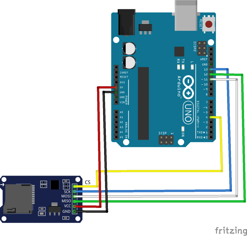
Circuit Diagram
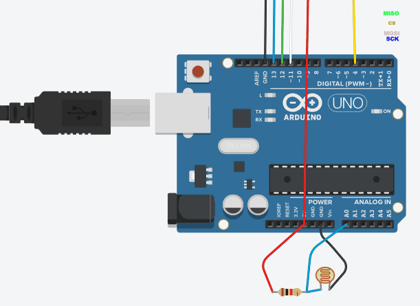
Here we have a circuit that captures brightness data through a combination of LDR and a resistor. Data gathered here will be saved on an SD Card using the SD card Module.
Code
					#include <SPI.h>
#include <SD.h>

File myFile;

void setup() {

  // Open serial communications and wait for port to open:
  Serial.begin(9600);

  while (!Serial) {
    ; // wait for serial port to connect. Needed for native USB port only
  }


  Serial.print("Initializing SD card...");

  if (!SD.begin(4)) {
    Serial.println("initialization failed!");
    return;
  }

  Serial.println("initialization done.");

  // open the file. note that only one file can be open at a time,
  // so you have to close this one before opening another.
  myFile = SD.open("data.csv", FILE_WRITE);

  // if the file opened okay, write to it:
  if (myFile) {
    Serial.print("Writing to Data to data.csv");
    myFile.println("Time, Data");
    // close the file:

    myFile.close();
    Serial.println("done.");
 }

 else {
    // if the file didn't open, print an error:
    Serial.println("error opening test.txt");
  }

  // re-open the file for reading:

}

void loop() {
  int t = millis() / 1000; // keep track of time after strating


  String buf = "";  //Data String
  buf += String(t);
  buf += ",";
  buf += String(analogRead(0));


  myFile = SD.open("data.csv", FILE_WRITE); // Open File
  myFile.println(buf);                      // Write data
  myFile.close();                           // Close File
  delay(5000);                          // Wait 5 second and repeat
}
How the Code Works
The complexity of the SPI protocol is abstracted away from the user through the Arduino code structure. The SD library simplifies it further. The comments within the code explain the purpose of each line of code.
TIP: When working with SD cards and File objects, ensure that you close the file after each data logging session. Note that data is not automatically saved into the SD card until it is closed.
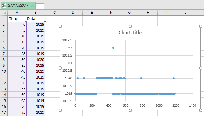
After the code is uploaded to Arduino, wait for a period of 5-10 minutes. Sensor data is logged into a CSV file named “Data.csv” created by the Arduino inside the SD card every 5 seconds. These data can be viewed in Excel.
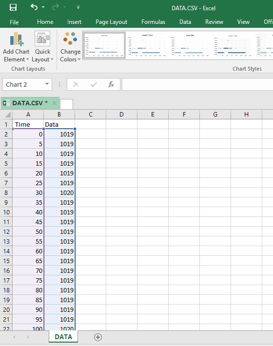
From this data, a graph can be plotted which can provide useful insights into your area of interest.
SHOP THIS PROJECT
-