Find tips and advices on using your microcontroller i/o ports in this article!
Introduction
The Arduino ecosystem has made it easy to work with microcontrollers. However, because of this, you may miss out on certain concepts related to your device’s characteristics. Here is a guide to help you dig deeper into the functions of your microcontroller i/o ports.
On Using Your Micorcontroller Digital Input Pins
Don't leave your Digital Inputs Floating
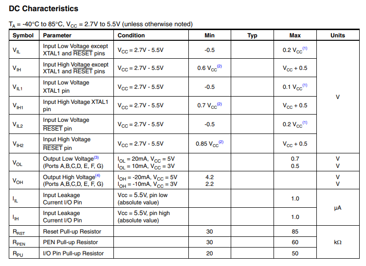
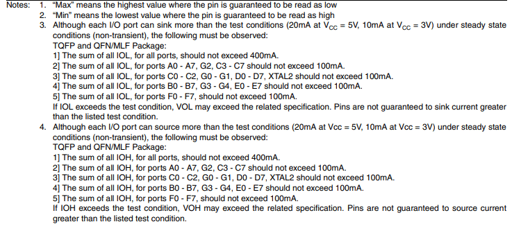
Digital inputs have a defined value. You’ll usually see this in the Electrical Specifications of your Datasheet. It should be labeled as Digital input VHigh Min and Max or VLow Min and Max. Because of this, you should avoid getting input values in between these min and max values. When you leave your digital inputs floating, it’s most likely that you’ll get random values. You can set your input port to turn on an internal pull-up or pull-down resistor if your port has this capability. Otherwise, tie up these inputs externally to Vcc or GND through external pullup or pulldown resistors.
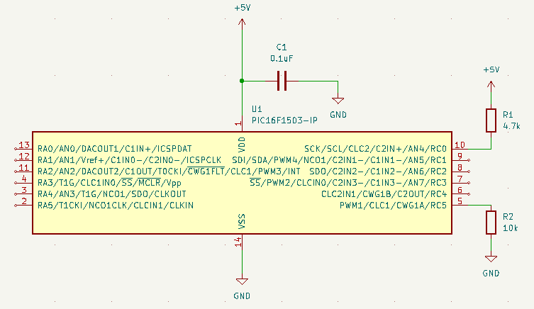
The value used for a pull up or pull down resistor should be in the range of at least 10 times lower than the internal impedance of the input pin. Generally, this input impedance should be in the 100k – 1M ohm range. With this, choose a value appropriately. Too high a value can create a large voltage drop on the resistor that can hamper the valid logic voltage range on the input pin.
On using Push Buttons on your DigitaL I/O pins
Push buttons help microcontrollers interact with the outside world through finger presses from a user. Push button inputs are still digital inputs, so make sure you enable an internal or external pull-up or pull-down resistor for them. Additionally, debounce these inputs either through hardware or software to eliminate glitchy values.
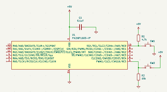
The figure above implements RC0 as an active low switch input while RC5 is an active high. Note that since there are no series protection resistors, avoid configuring these ports as outputs.
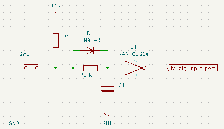
A hardware debouncer is composed of a diode, capacitor, resistor, and a Schmitt trigger. A more dedicated post should explain its operation in detail. For now see that the RC combination act as a low-pass filter for your switch, the diode acts to shorten the time of charging of the capacitor and, the Schmitt trigger ensures you have a digital waveform output fed to your input pin.
Another method you can use to detect button presses reliably is to use a software debounce routine or statements on your firmware. The debounce routine/statement can be simple such as adding a delay once you detect a button press. It can also be more complex such as determining all or some of the states of a switch bounce using timers. In either case, your end goal is simply to know when a user has pressed the push button switch.
Here is a fairly simple code to debounce your push button switch using a delay.
					// define buttons
#define button1 A3
#define button2 A4
#define button3 A0
#define button4 A1
					void setup(void)
{
  while (!Serial);  // Required for Flora & Micro
  delay(500);

  // prepare button inputs
  pinMode(button1, INPUT_PULLUP);
  pinMode(button2, INPUT_PULLUP);
  pinMode(button3, INPUT_PULLUP);
  pinMode(button4, INPUT_PULLUP);
					  if(digitalRead(button2) == 0)
  {
    delay(500);
    ble.print("AT+BleHidControlKey=");
    ble.println("HOME");
    if( ble.waitForOK() )
    {
      Serial.println( F("OK!") );
    }else
    {
      Serial.println( F("FAILED!") );
      //Failed, probably pairing is not complete yet
      Serial.println( F("Please make sure Bluefruit is paired and try again") );
    }

  }
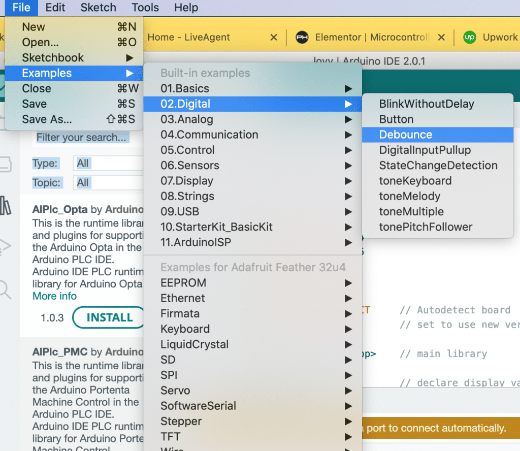
On another note, you can create a more complex debounce routine using code from the Arduino Examples menu.
					/*
  Debounce

  Each time the input pin goes from LOW to HIGH (e.g. because of a push-button
  press), the output pin is toggled from LOW to HIGH or HIGH to LOW. There's a
  minimum delay between toggles to debounce the circuit (i.e. to ignore noise).

  The circuit:
  - LED attached from pin 13 to ground through 220 ohm resistor
  - pushbutton attached from pin 2 to +5V
  - 10 kilohm resistor attached from pin 2 to ground

  - Note: On most Arduino boards, there is already an LED on the board connected
    to pin 13, so you don't need any extra components for this example.

  created 21 Nov 2006
  by David A. Mellis
  modified 30 Aug 2011
  by Limor Fried
  modified 28 Dec 2012
  by Mike Walters
  modified 30 Aug 2016
  by Arturo Guadalupi

  This example code is in the public domain.

  https://www.arduino.cc/en/Tutorial/BuiltInExamples/Debounce
*/

// constants won't change. They're used here to set pin numbers:
const int buttonPin = 2;  // the number of the pushbutton pin
const int ledPin = 13;    // the number of the LED pin

// Variables will change:
int ledState = HIGH;        // the current state of the output pin
int buttonState;            // the current reading from the input pin
int lastButtonState = LOW;  // the previous reading from the input pin

// the following variables are unsigned longs because the time, measured in
// milliseconds, will quickly become a bigger number than can be stored in an int.
unsigned long lastDebounceTime = 0;  // the last time the output pin was toggled
unsigned long debounceDelay = 50;    // the debounce time; increase if the output flickers

void setup() {
  pinMode(buttonPin, INPUT);
  pinMode(ledPin, OUTPUT);

  // set initial LED state
  digitalWrite(ledPin, ledState);
}

void loop() {
  // read the state of the switch into a local variable:
  int reading = digitalRead(buttonPin);

  // check to see if you just pressed the button
  // (i.e. the input went from LOW to HIGH), and you've waited long enough
  // since the last press to ignore any noise:

  // If the switch changed, due to noise or pressing:
  if (reading != lastButtonState) {
    // reset the debouncing timer
    lastDebounceTime = millis();
  }

  if ((millis() - lastDebounceTime) > debounceDelay) {
    // whatever the reading is at, it's been there for longer than the debounce
    // delay, so take it as the actual current state:

    // if the button state has changed:
    if (reading != buttonState) {
      buttonState = reading;

      // only toggle the LED if the new button state is HIGH
      if (buttonState == HIGH) {
        ledState = !ledState;
      }
    }
  }

  // set the LED:
  digitalWrite(ledPin, ledState);

  // save the reading. Next time through the loop, it'll be the lastButtonState:
  lastButtonState = reading;
}
On Using your Microcontroller's Digital Output pins
Different kinds of microcontrollers employ different characteristics on their digital pins configured as output. It can be that their outputs can supply a large amount of current that can drive an LED. On the other hand, it can be that their output can supply current just enough to communicate with a sensor or another microcontroller. Check your micorcontroller’s datasheet and look for both output current per pin and output current per group or overall ports.
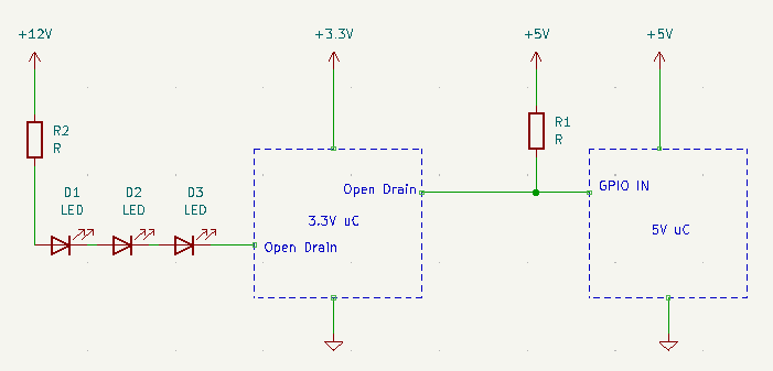
Digital Outputs in Open Drain Mode
Some microcontrollers allow open drain outputs. When turned on, these outputs drive its external pin to ground through one internal MOSFET inside the chip. This is unlike plain GPIOs, which have push-pull circuitry (which actually has two complementary internal MOSFETs) that simply outputs a high or low value to communicate with sensors or other peripherals.
An open drain output has the ability to sink current generated from a higher or lower valued voltage source than your microcontroller’s Vdd. This means you can drive peripherals or communicate with other IC’s that has a different supply voltage.
Conclusion
You’ve just learned different concepts related to your microcontroller’s i/o ports. Digital inputs should always have defined logic levels for you to get reliable data. This can be done by employing pull ups or pull down resistors. You’ve also learned how to use push buttons properly. Additionally, your output ports have differrent characteristics you can take advantage of when driving your circuits.