Curious about how a Zener diode works as a voltage reference? Continue reading this article to find out.
Introduction
Zener diodes are very useful components found in your workbench. They have several applications. You can use them as clippers, voltage references, and voltage spike protectors, to name a few. Here, you’ll learn to use Zener diodes as a voltage reference in more detail. They have several advantages over the traditional resistor voltage divider reference.
The Unique Characteristics of a Zener Diode
A Zener diode behaves like a regular PN junction diode in the forward bias region. This means it will only conduct when a voltage of 0.7V or greater is applied. This threshold voltage is the Vforward voltage.
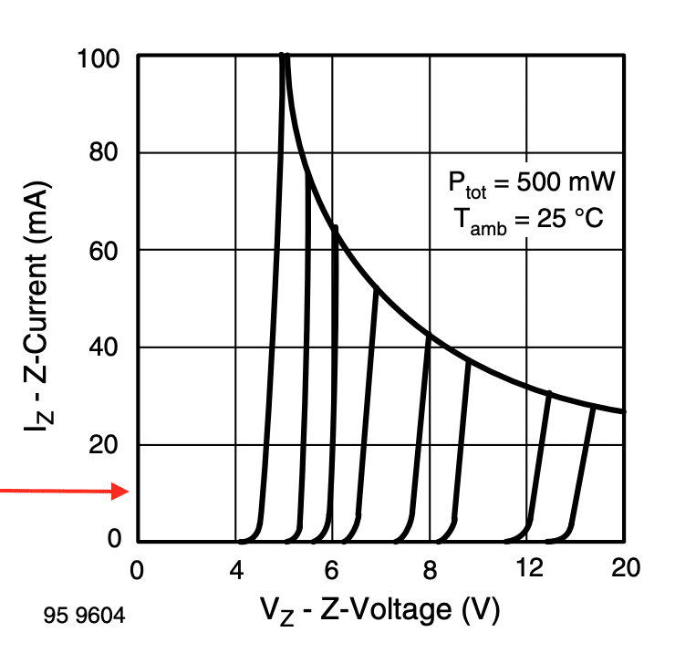
In the reverse bias region, a Zener diode behaves differently. Initially, the Zener remains reverse-biased like a PN junction diode when a reverse voltage Vz less than VZ (the Zener Breakdown Voltage) is applied to it. Ultimately, the Zener diode conducts as the voltage approaches VZ. The knee indicates this on the curve on the left side of the graph. This conduction is controlled as the voltage across the Zener remains constant with varying currents.
Biasing the Zener Diode Along with a Series Resistor
Biasing a Zener diode is simple. You just need to apply a voltage several times greater than VZ (or the Zener Breakdown Voltage).
So, for example, if you have a 5V zener diode, you can easily bias this with a +12V DC source along with a limiting resistor.
Using the Zener Diode as a Voltage Reference
The Zener diode’s reverse breakdown voltage characteristics allow it to be used as a stable voltage reference. With this, you can generate a constant voltage for different loads without worrying too much about the loading effect as long as you’re in spec with Zener’s datasheet.
Note that this zener diode has an absolute maximum rating of 500mW for its power. You have to be well below this spec.
Next, find the part number needed close to your intended voltage. Here, for example, a Zener voltage of 4.7V is used.
As you can see, the device is tested to have a Vz of 4.7V at Izt1, which is 20mA. With this, you can compute the needed series resistor with your Zener. Sometimes, you may also find that the Vz is stable at lower levels of Izt but this may require testing.
Ideally, the Zener acts like a constant voltage source which theoretically has zero ohms source resistance, but this is not true in a real-world case. On the far right, you should see a corresponding dynamic resistance value based on your chosen IZTx. You can use this as a reference. Note that your maximum allowable load will also be affected by both IZTx and Zz values.
Usually, you use Zeners as voltage references for the inputs of your MCUs, Op-Amps, or the base or gate of your transistor. As these inputs have a very little drawn current (usually in the uA range), you don’t have to worry much about the loading effect on your Zener diode circuit.
Sample Application 1
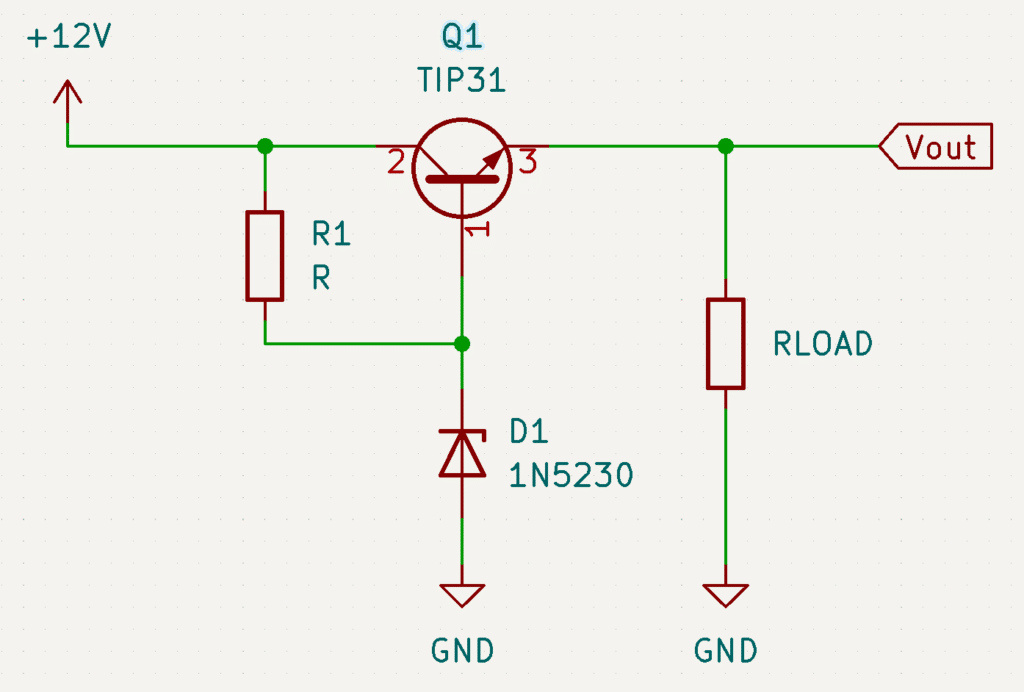
Here, a Zener diode D1 is used as a reference for a simple regulated power supply. The regulated voltage output is approximately 5V coming from a 12V input source. Q1 acts as a pass transistor.
The voltage reference is composed of R1 and D1. The input draw of the base current of Q1 should only be small (a few mA). With this, you can readily use a Zener current equal to Izt1 taken from the table above (@ 20mA). You can get R1 through the equation:
VR1.= Vcc – 4.7V
VR1 = 12V – 4.7V
VR1 = 7.3V
R1 = VR1 / Iz1
R1 = 7.3V / 20mA
R1 = 365 ohms
Sample Application 2
If you find the Zener current a bit large for your power-constrained application (such as in microcontrollers), you can create an alternate estimate of the Zener current. Generally, using only 10% of the maximum power dissipation of a component such as the Zener should suffice for it to work satisfactorily. See the computation below.
Pzmax = 500mW
Pzmin = 10% of (Pzmax)
Pmin = 50mW
@Vz = 4.7V
Iz = 50mW / 4.7V
Iz = 10.63mA
@VR1 = 7.3V
R1 = VR1 / Iz
R1 = 7.3V / 10.63mA
R1 = 686 ohms
You can try to verify your obtained Zener current through the Z-Current vs. Z-Voltage graph on your datasheet if this satisfies your requirements.