This article will help you understand voltage dividers and their application as voltage references so you can use them effectively on your everyday circuits.
Introduction
You may have gone through voltage dividers upon learning introductory electronics fundamentals. If not, this is an excellent place to start. Voltage dividers and references are important circuit blocks for generating pre-determined voltage outputs. Once you learn how to set up stable voltage dividers, you are one step closer to having more robust and precise projects.
Voltage Divider Circuits
A voltage divider is composed of two or more resistors in series. The series circuit generates the reference voltage/s.
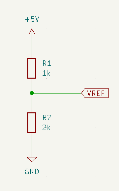
Voltage Divider Circuit w/ two Series Resistors
Consider the simple series voltage divider circuit below:
Here we have R1 as 1k and R2 as 2k. The general formula to get the voltage drop for each resistor is:
VR1 = VCC * (R1 / (R1 + R2))
VR2 = VCC * (R2 / (R1 + R2))
To get VREF, we use the value of VR2
VREF = 5V * (2k / (1k + 2K))
VREF = 3.33V
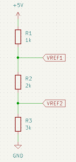
Voltage Divider Circuit w/ Multiple Series Resistors
Similarly, you can cascade several series resistors in your voltage divider circuit. Consider the circuit below:
Here you have R1 as 1k and R2 as 2k, and R3 as 3k. The general formula to get the voltage drop for each resistor is:
VR1 = VCC * (R1 / (R1 + R2 + R3))
VR1 = 5V * (1k / (1k + 2k + 3k))
VR1 = 0.833 V
VR2 = VCC * (R2 / (R1 + R2 + R3))
VR2 = 5V * (2k / (1k + 2k + 3k))
VR2 = 1.667 V
VR3 = VCC * (R3 / (R1 + R2 + R3))
VR3 = 5V * (3k / (1k + 2k + 3k))
VR3 = 2.50 V
To get VREF1 we add the values of VR2 + VR3
VREF1 = VR2 + VR3
VREF1 = 1.667V + 2.50V
VREF1 = 4.167 V
To get VREF2, we use the value of VR3
VREF = VR3
VREF = 2.50 V
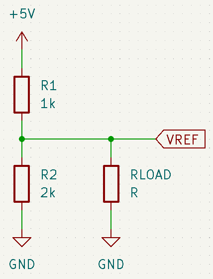
Using the Voltage Divider as Reference
A series resistor voltage divider can be used as a voltage reference for different circuits. These circuits include power supplies, voltage regulators, microcontroller voltage references, and others.
To use the voltage divider correctly, you must ensure it will output acceptable values for a given load at its reference point.
Usually, the load’s resistance should be ten times greater (or more) than the equivalent source resistance of the divider.
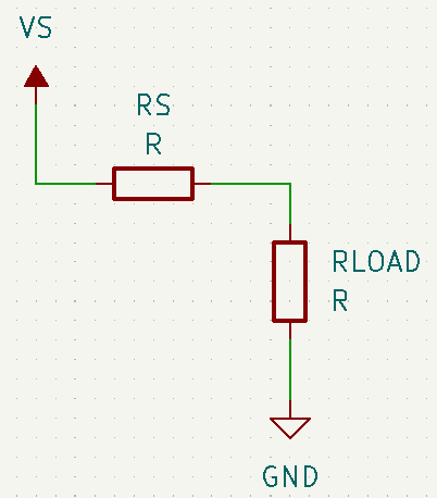
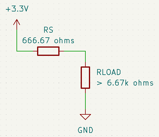
The equivalent source resistance of the divider can be computed using Thevenin’s Theorem. The theorem will turn your divider circuit into a voltage source (equal to VREF) in series with an equivalent series resistance:
The computation for RS is:
Rs = (R1 * R2) / (R1 +R2)
Rs = (1k * 2k) / (1k + 2k)
Rs = (1k * 2k) / (1k + 2k)
Rs = 666.67 ohms
and you’ll be using VREF as VS which is 3.33V
This means that your load should be at least 6.67 k ohms or greater for your voltage reference to be theoretically close to your intended vaue.
Here, you’ll find that the voltage across the load will be approximately 3.03V with only about 0.3V voltage lost due to voltage drop on the equivalent source resistor of the voltage divider circuit.
VLOAD = VS * (RLOAD / (RS + RLOAD))
VLOAD = 3.33V * (6.67K / (666.67 + 6.67k))
VLOAD = 3.03 V
More Resources
If you are unsatisfied with the performance of resistive voltage dividers used as voltage references, you can look into other means of doing it. You can also look into our Zener Diodes used as voltage reference blog that will publish next week.