Introduction
In this tutorial, we will learn about the KY-032 module, how the module detects an obstacle and we will build a simple project using the KY-032 module and an Arduino.
Obstacle Avoidance Sensor KY-032
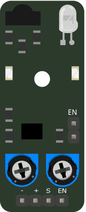
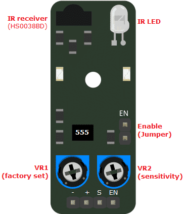
The KY-032 Module will be our main component for this tutorial. This module has an infrared LED, an infrared receiver, and 555 timer IC mounted on a PCB. Figure 1 shows the module in fritzing.

Pinout
The KY-032 module has four pins.
| Pin | Description |
|---|---|
| (-) | Ground |
| (+) | +5V |
| S | Signal |
| EN | Enable |
How the Ky-032 Works

The module produces a 38KHz square wave primarily made-up by the 555 Timer IC and VR1. This 38KHz pulse is used to switch on/off the IR LED. If there is an object in front of the IR LED, the infrared pulses are reflected and some of the reflected IR is detected by the IR receiver (HS0038BD). This would tell the module that there is an obstacle and will pull the signal pin S to LOW. If there is no obstacle, pin S will be HIGH. VR2 is used to adjust the distance the obstacle is detected. The module has a detection range of 2~40cm.
The EN pin and EN jumper are provided to have control over the module detection. Put a jumper at EN to have the module always enabled. If you want to have control over the module enable/disable, remove the jumper and connect the EN pin to HIGH to enable or LOW to disable.
Project - Arduino Obstacle Indicator
After learning about the KY-032 module and how it works, it is now time to build a project using the module. Our project will use the KY-032 module to detect an obstacle, display a message on the serial monitor, and control the Arduino’s built-in LED.
Project Components
For this project, we need the following components:
- Arduino Uno board (1 pc.)
- KY-032 Obstacle Avoidance Sensor (1 pc.)
- Jumper wires
Wiring Diagram

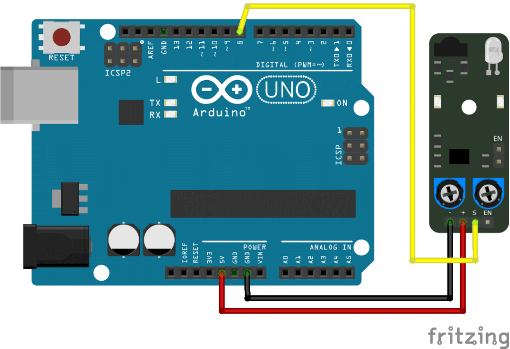
The KY-032 module pins are connected to the Arduino Uno board as follows:
| Component Pin | UNO Board Pin |
|---|---|
| (-) | Ground |
| (+) | +5V |
| S | 8 |
| EN | No Connection |
The Code
Below is the Arduino sketch for our project. I have added comments to explain important parts of the code. Save the code as KY-032.ino and upload it to your Arduino board.
					// Arduino and KY-032 module
// Note: Put a jumper on the EN pins
void setup ()
{
pinMode (13, OUTPUT); // built-in LED pin set to output
pinMode (8, INPUT); // module signal output connected to Arduino pin 8
Serial.begin(9600); // initialize serial
}
void loop ()
{
if (digitalRead(8) == LOW) { // if module detects an obstacle,
Serial.println("Obstacle Detected"); // show message on serial monitor and
digitalWrite (13, HIGH); // switch-On built-in LED
}
else {
Serial.println("No Obstacle");
digitalWrite (13, LOW);
}
}
Project Test
Apply power to your Arduino Uno board and open the Serial Monitor in the Arduino IDE. Arduino will send a message “Obstacle Detected” to the serial monitor if there is an object in front of the module and switch on the built-in LED. If there is no obstacle, the message on the serial monitor will be “No Obstacle” and the LED will be off. Adjust the detection distance via VR1.


