Introduction
In this tutorial, we will learn about the APDS-9960 module, how it works and we will build a simple project using the APDS-9960 and an Arduino.
The Module
The APDS-9960 module has multiple functionalities: measuring ambient light and color (clear, red, green, and blue), proximity detection, and gesture sensing.
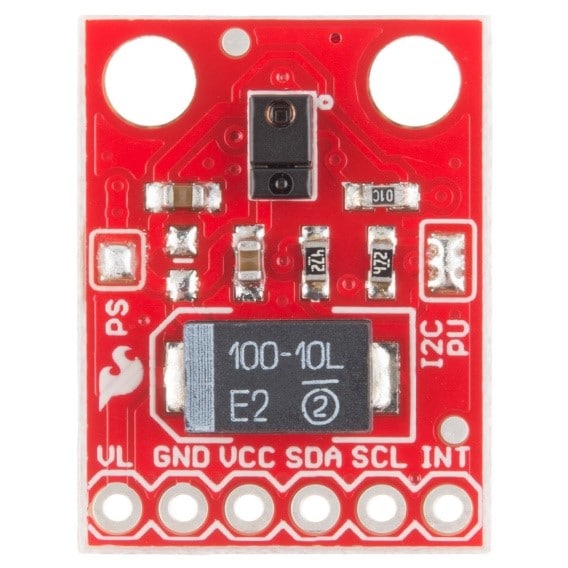
Pin Out
The APDS-9960 has six pins.
| Pin | Description |
|---|---|
| VL | Optional power to the IR LED if PS jumper is disconnected. Must be 3.0 - 4.5V |
| GND | Connect to Ground |
| VCC | Used to power the APDS-9960 sensor. Must be 2.4 - 3.6V |
| SDA | IIC data |
| SCL | IIC clock |
| INT | External interrupt pin. Active LOW on interrupt event |
How Does It Work?
The APDS-9960 has a built-in multifunctional infrared sensor and uses IIC communication protocol to communicate with the microcontroller.
Project - Arduino Gesture Monitor
This project will demonstrate how the APDS-9960 module shows the hand gesture performed in the serial monitor.
Components
- 1 x Uno Board (Arduino Compatible)
- 1 x RGB Motion Direction Identification Infrared Sensor Module – APDS-9960
- Jumper Wires
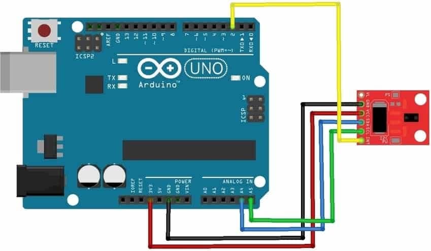
Wiring Diagram
The APDS-9960 module pins are connected to the Arduino Uno board as follows:
| Module Pin | UNO Board Pin |
|---|---|
| GND | GND |
| VCC | VCC |
| SDA | A4 |
| SCL | A5 |
| INT | 2 |
| GND | GND |
| VCC | VCC |
The Code
Download the library for the module first before proceeding. The library is available here; Arduino APDS9960 Library
Once the library is installed, the program code can be uploaded. For this project the GestureSensor.ino program code will be used and can be found in the examples folder.
					/*
  APDS-9960 - Gesture Sensor

  This example reads gesture data from the on-board APDS-9960 sensor of the
  Nano 33 BLE Sense and prints any detected gestures to the Serial Monitor.

  Gesture directions are as follows:
  - UP:    from USB connector towards antenna
  - DOWN:  from antenna towards USB connector
  - LEFT:  from analog pins side towards digital pins side
  - RIGHT: from digital pins side towards analog pins side

  The circuit:
  - Arduino Nano 33 BLE Sense

  This example code is in the public domain.
*/

#include <Arduino_APDS9960.h>

void setup() {
  Serial.begin(9600);
  while (!Serial);

  if (!APDS.begin()) {
    Serial.println("Error initializing APDS-9960 sensor!");
  }

  // for setGestureSensitivity(..) a value between 1 and 100 is required.
  // Higher values make the gesture recognition more sensitive but less accurate
  // (a wrong gesture may be detected). Lower values makes the gesture recognition
  // more accurate but less sensitive (some gestures may be missed).
  // Default is 80
  //APDS.setGestureSensitivity(80);

  Serial.println("Detecting gestures ...");
}
void loop() {
  if (APDS.gestureAvailable()) {
    // a gesture was detected, read and print to Serial Monitor
    int gesture = APDS.readGesture();

    switch (gesture) {
      case GESTURE_UP:
        Serial.println("Detected UP gesture");
        break;

      case GESTURE_DOWN:
        Serial.println("Detected DOWN gesture");
        break;

      case GESTURE_LEFT:
        Serial.println("Detected LEFT gesture");
        break;

      case GESTURE_RIGHT:
        Serial.println("Detected RIGHT gesture");
        break;

      default:
        // ignore
        break;
    }
  }
}
Project Test
Wire the components to the Arduino as demonstrated in the wiring diagram. Connect the Arduino to a PC and upload the program. Open the Serial Monitor in the Arduino IDE and the hand gesture performed in front of the sensor will be displayed.


