-
Sale!

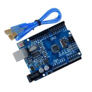
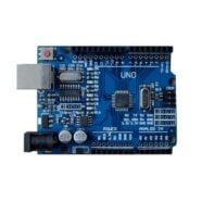
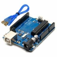
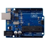
UNO R3 ATmega328P CH340 Development Board – Arduino Compatible with USB Cable
Original price was: $23.95.$22.95Current price is: $22.95. Add to cart -
Sale!
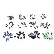
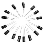
Aluminium Electrolytic 12 Value Capacitor Kit – Pack of 120
Original price was: $15.95.$14.95Current price is: $14.95. Add to cart -