Introduction
Having a remotely controlled power supply is an interesting feature that any electronics hobbyist would want. Imagine having equipment in a remote location where you need to change some functions. The only way to do it is by changing a voltage value in the circuit. You may also want to control some analog functions on your board or simply turn on and off some peripherals remotely.
How it Works
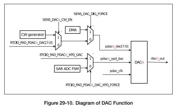
ESP32 DAC Peripheral
Your ESP32 has an on-chip DAC. In fact, it has two DACs. DAC stands for Digital-to-Analog Converter. This peripheral can convert any digital value in your program to an analog voltage. This analog voltage supports references from the chips power supply which approximately ranges from 0V to VDD(3.3V). You can program the DAC’s value anywhere in your code.
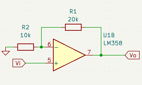
LM358 OP-AMP
The output of the ESP32’s DAC is limited to the ESP32’s own voltage supply which is 3.3V maximum. This is fairly low when you’re dealing with power supply voltage ranges. With this, you’ll need some sort of amplification. An LM358 General Purpose Op-Amp is fit for this. It’s a low-cost op amp that can operate on DC power supplies. Here, a voltage gain of 3 is used in a non-inverting configuration to amplify the DAC’s output. This effectively triples the 3.3V limitation of the DAC.
Simple Buffer
Your voltage source should have adequate power to supply current to its load. The output of the LM358 isn’t enough. With this, a simple power transistor (TIP31C) is used in an emitter-follower configuration. Now, you don’t have to worry about your voltage source dropping its value when it becomes loaded.
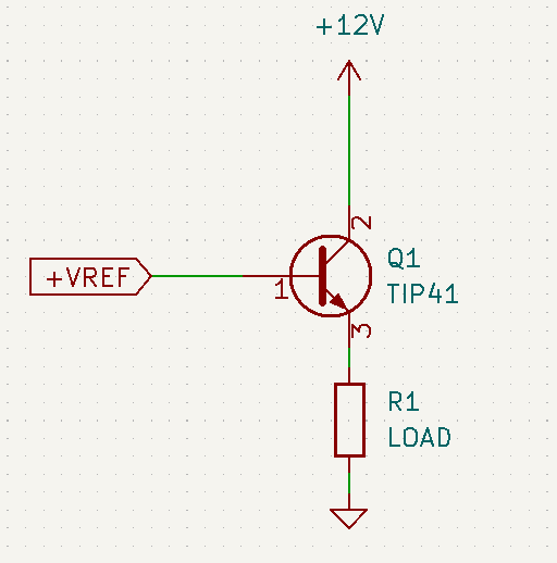
The input impedance of the emitter follower is Beta * R1. In effect, you get a high input impedance that acts to buffer your VREF source.
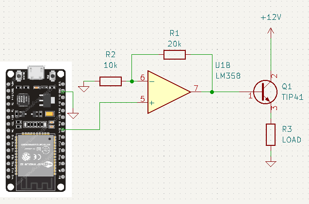
The Complete Circuit
Writing Firmware
Before you can program ESP32 on Arduino, you should set things up on the IDE. Take a look at this guide if you haven’t set things up.
You can start to write firmware for your DAC. Below is the complete code for it.
					#define DACpin  25

const float ref_voltage PROGMEM = 3.3;

float OUTvoltage;

float DACvoltage;

uint8_t DACvalue;

void setup() {

  // put your setup code here, to run once:

  Serial.begin(9600);

  OUTvoltage = 5.0;

  DACvoltage = ((OUTvoltage+0.7)/3);

  DACvalue = (DACvoltage/ref_voltage)*255*1.0;

  Serial.print("OUTvoltage = "); Serial.println(OUTvoltage);

  Serial.print("DACvoltage = "); Serial.println(DACvoltage);

  Serial.print("DACvalue = "); Serial.println(DACvalue);

  dacWrite(DACpin, DACvalue);

}

void loop() {

  // put your main code here, to run repeatedly:

}
The Outvoltage variable is your target reference voltage. DACvoltage is the output of your DAC, while DACvalue is the integer value of your DAC.
The Arduino IDE has an example code for your ESP32 to act as a simple web server. Through this, you’ll be able to browse a simple webpage on your ESP32 and interact with it through GET requests on your device’s web browser. This is something similar to our previous blog here.
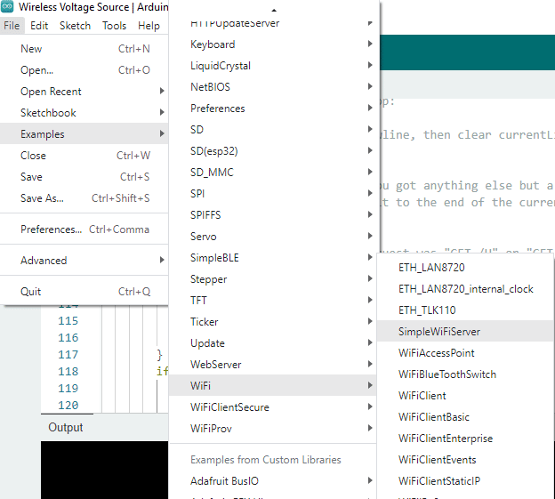
Open Arduino IDE and then click File -> Examples -> WiFi -> SimpleWiFiServer
This code is a good basis to start simple WiFi web server development. You’ll have to edit some things to make it work. You’ll also have to add code to make it work with your Voltage Source circuit.
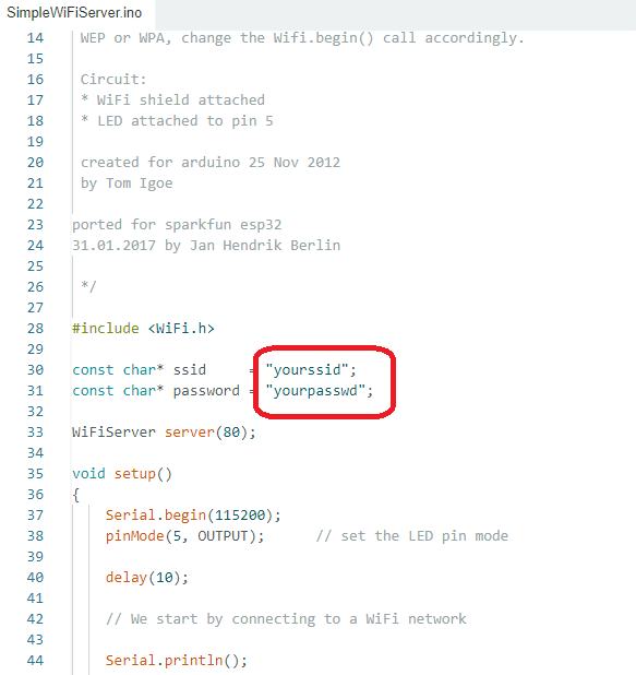
Edit this with your WiFI username and password.
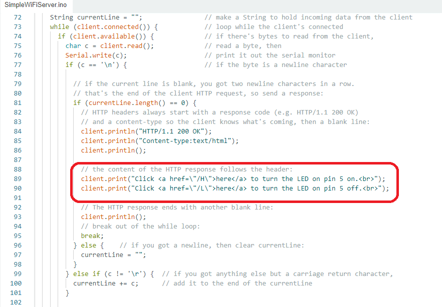
You’ll edit this with your own text and html code for the custom voltages of your wireless voltage source to be seen on a web browser.
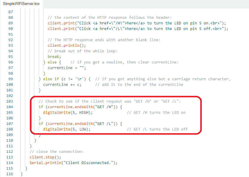
You’ll also edit this to define the execution of your ESP32’s DAC to output the correct voltages with their corresponding GET requests.
Here is the complete edited code together with the DAC code
#include <WiFi.h>
#define DACpin 25
const char* ssid = " Your Wifi";
const char* password = "Your password";
WiFiServer server(80);
const float ref_voltage PROGMEM = 3.3;
float OUTvoltage;
float DACvoltage;
uint8_t DACvalue;
void setup()
{
Serial.begin(115200);
pinMode(2, OUTPUT); // set the LED pin mode
delay(10);
// We start by connecting to a WiFi network
Serial.println();
Serial.println();
Serial.print("Connecting to ");
Serial.println(ssid);
WiFi.begin(ssid, password);
while (WiFi.status() != WL_CONNECTED) {
delay(500);
Serial.print(".");
}
Serial.println("");
Serial.println("WiFi connected.");
Serial.println("IP address: ");
Serial.println(WiFi.localIP());
server.begin();
}
int value = 0;
void loop(){
WiFiClient client = server.available(); // listen for incoming clients
if (client) { // if you get a client,
Serial.println("New Client."); // print a message out the serial port
String currentLine = ""; // make a String to hold incoming data from the client
while (client.connected()) { // loop while the client's connected
if (client.available()) { // if there's bytes to read from the client,
char c = client.read(); // read a byte, then
Serial.write(c); // print it out the serial monitor
if (c == '\n') { // if the byte is a newline character
// if the current line is blank, you got two newline characters in a row.
// that's the end of the client HTTP request, so send a response:
if (currentLine.length() == 0) {
// HTTP headers always start with a response code (e.g. HTTP/1.1 200 OK)
// and a content-type so the client knows what's coming, then a blank line:
client.println("HTTP/1.1 200 OK");
client.println("Content-type:text/html");
client.println();
// the content of the HTTP response follows the header:
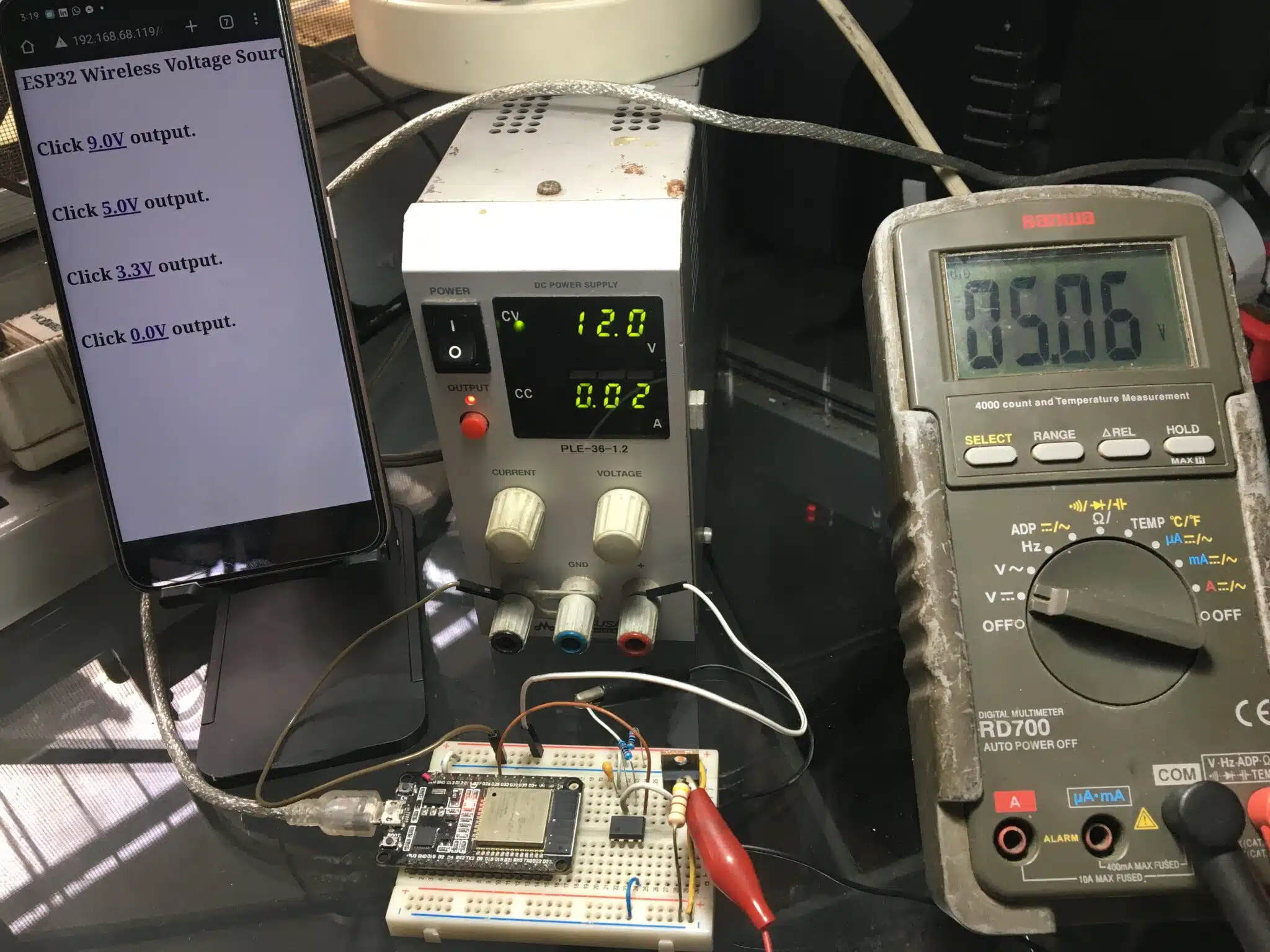
client.print("<h1>ESP32 Wireless Voltage Source</h1><br><br>");
client.print("<h1>Click <a href=\"/9.0V\">9.0V</a> output.</h1><br><br>");
client.print("<h1>Click <a href=\"/5.0V\">5.0V</a> output.</h1><br><br>");
client.print("<h1>Click <a href=\"/3.3V\">3.3V</a> output.</h1><br><br>");
client.print("<h1>Click <a href=\"/0.0V\">0.0V</a> output.</h1><br><br>");
// The HTTP response ends with another blank line:
client.println();
// break out of the while loop:
break;
} else { // if you got a newline, then clear currentLine:
currentLine = "";
}
} else if (c != '\r') { // if you got anything else but a carriage return character,
currentLine += c; // add it to the end of the currentLine
}
// Check to see if the client request was "GET /H" or "GET /L":
if (currentLine.endsWith("GET /3.3V")) {
OUTvoltage = 3.3;
DACvoltage = ((OUTvoltage+0.7)/3);
DACvalue = (DACvoltage/ref_voltage)*255*1.0;
dacWrite(DACpin, DACvalue);
}
if (currentLine.endsWith("GET /5.0V")) {
OUTvoltage = 5.0;
DACvoltage = ((OUTvoltage+0.7)/3);
DACvalue = (DACvoltage/ref_voltage)*255*1.0;
dacWrite(DACpin, DACvalue);
}
if (currentLine.endsWith("GET /9.0V")) {
OUTvoltage = 9.0;
DACvoltage = ((OUTvoltage+0.7)/3);
DACvalue = (DACvoltage/ref_voltage)*255*1.0;
dacWrite(DACpin, DACvalue);
}
if (currentLine.endsWith("GET /0.0V")) {
dacWrite(DACpin, 0);
}
}
}
// close the connection:
client.stop();
Serial.println("Client Disconnected.");
}
}
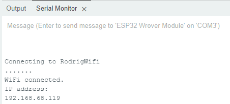
After running your code make sure that you open the serial monitor. Here you’ll find the address of the webpage you need to access to make your wireless voltage source run.
And here is the circuit in action.