Do you want to add more functions to your fan speed controller? Continue reading the rest of this article to find out.
Introduction
Previously, this blog presented how to use the LED PWM peripheral of an ESP32 to vary the speed of a DC fan. Here, an Arduino UNO board will be used and it will use a port with PWM functionality. You’ll learn how to program the PWM to be able to control the speed of your fan. You’ll also put in different fan speed modes. Additionally, you’ll learn how to save this mode in non-volatile memory so that it won’t get erased even if you turn your Arduino OFF.
The Arduino UNO's PWM Peripheral
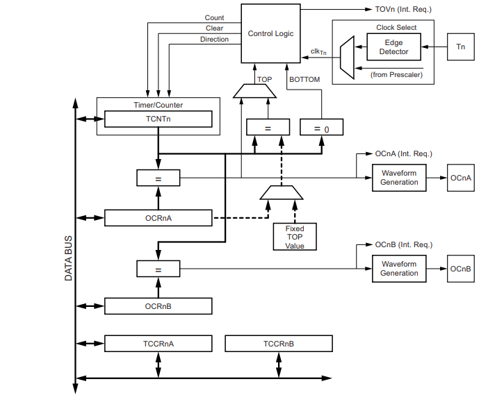
Basically, the UNO has two kinds of PWM peripherals. It has 8-bit and 16-bit PWM peripherals. The 8-bit PWM will be the one used in this fan speed controller. This PWM is composed of an 8-bit Timer/Counter with PWM functionality. It has Output Compare Modules along with Frequency Generators.
To use the UNO’s PWM you’ll use the analogWrite( ) function with the syntax:
analogWrite(pin, value)
where:
- pin is the digital PWM pin
- value is a value from 0 – 255. 0 means OFF, 255 means 100% duty cycle, and the in-between values scale up to the corresponding %Duty Cycle
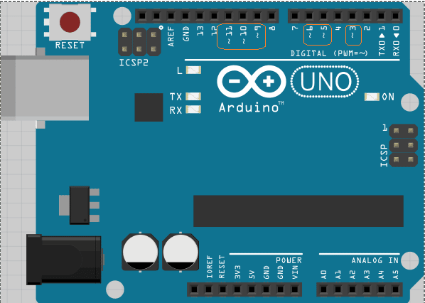
Your UNO has several PWM pins. Use any Digital Pin as seen below with the ~ sign.
Arduino UNO's EEPROM
Fortunately, the Arduino UNO’s chip (the ATMEGA328) has built-in EEPROM inside it. You can use this feature to save valuable info even if power has been cut off from your circuit. This is the perfect setup for this multi-mode fan speed controller. Here, you can store your fan’s speed mode at the time when you decide to change modes. You don’t have to worry, the UNO’s EEPROM can handle a very large number of write/erase cycles.
ATMEGA328 EEPROM Characteristics:
- 1 byte per memory location
- A total of 1024 bytes total
- 100,000 write/erase cycles
You’ll use the eeprom_write_byte() and the eeprom_read_byte() functions to write and read values from the corresponding EEPROM locations.
eeprom_write_byte(location, value)
value = eeprom_read_byte(location)
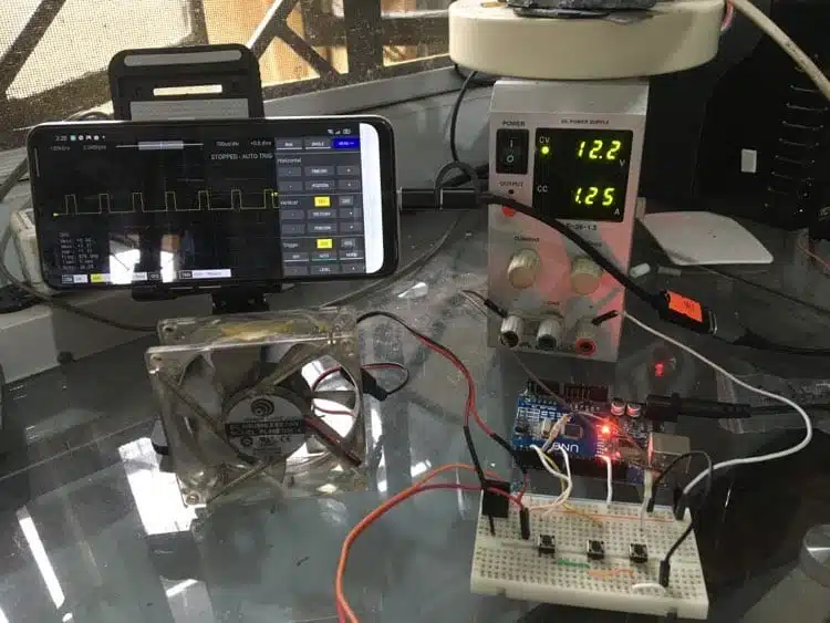
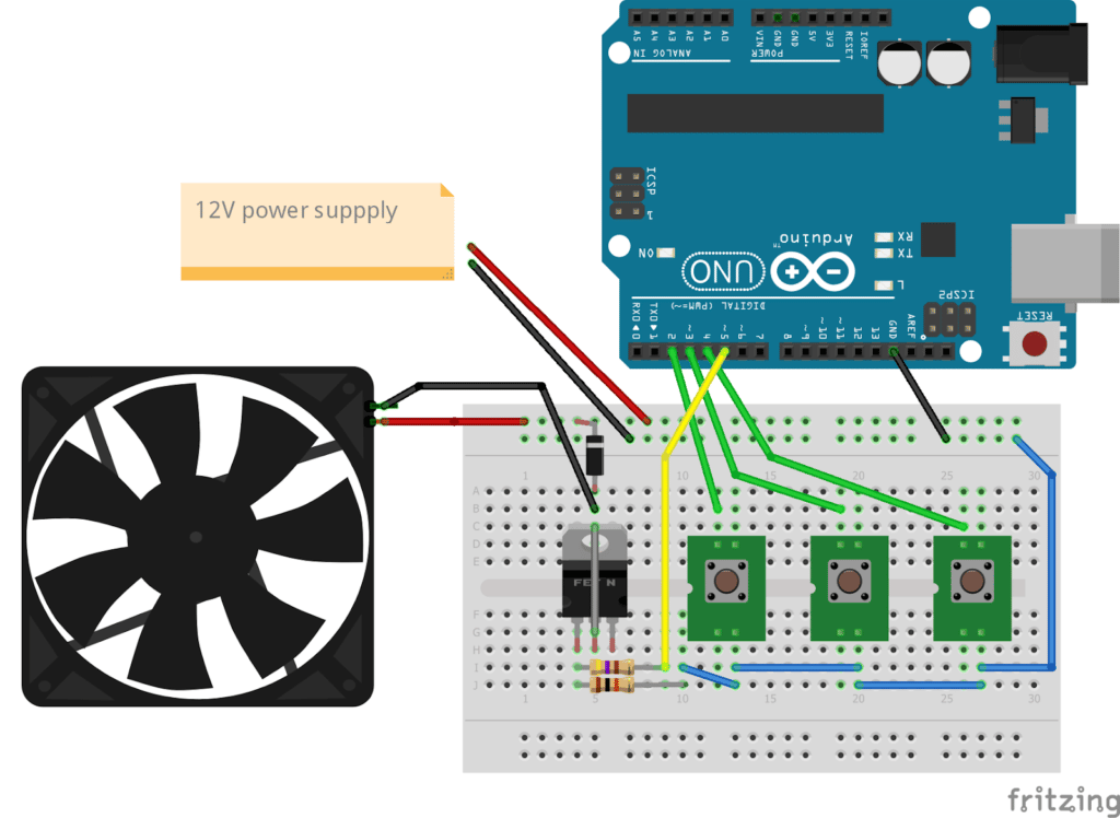
Wiring Diagram
Wire up the circuit below. This circuit contains the following parts:
- Arduino UNO
- N-Channel Power Mosfet transistor
- 10k ¼ W resistor
- 470 ohm ¼ W resistor
- DC CPU Fan
- 12V Power Supply (1A or above)
- 3x tact switches
- 1N4001 diode (back-emf protect)
- Breadboard
- Jumper wires
The Code
Here is the complete code for this multi-mode fan speed controller with memory function:
					#define low     64
#define medium  128
#define high    250

#define btn1  2
#define btn2  3
#define btn3  4

#define pwm_out 5

bool btn_stat;

uint8_t btn_read1, btn_read2, btn_read3;


uint8_t mySpeedVar;

void setup() {
  // put your setup code here, to run once:
  pinMode(btn1, INPUT_PULLUP);
  pinMode(btn2, INPUT_PULLUP);
  pinMode(btn3, INPUT_PULLUP);

  mySpeedVar = eeprom_read_byte(0);

  if(mySpeedVar != 0xFF) // if 0xFF then fan has no mode yet wait for user to select a mode
    analogWrite(pwm_out, mySpeedVar);   // else output mySpeed

  Serial.begin(9600);
}

void loop() {

  btn_read1 = !digitalRead(btn1);
  btn_read2 = !digitalRead(btn2);
  btn_read3 = !digitalRead(btn3);


  if(btn_read1 || btn_read2 || btn_read3)
  {
    delay(300); // debounce
    btn_stat = true;
  }else{
    btn_stat = false;
  }

  switch (btn_stat) {

    case true:
    if (btn_read1)
    {
      analogWrite(pwm_out, low);
      eeprom_write_byte(0, low);
    }else
        if (btn_read2)
        {
          analogWrite(pwm_out, medium);
          eeprom_write_byte(0, medium);
        }else
            if (btn_read3)
            {
              analogWrite(pwm_out, high);
              eeprom_write_byte(0, high);
            }

    break;

    case false:
    break;

    default:
    break;
  }

}
Code Explained
Basically, there are 3 buttons named btn1, btn2, and btn3 that are connected to your digital i/o port. The button’s values will be stored in byte variables btn_read1, btn_read2, and btn_read3. A btn_stat boolean variable is monitored to know if a button was pressed. In case the btn_stat becomes true, the analogWrite() function will be invoked to change the PWM output. Additionally, the current speed mode will be saved at location 0 of the UNO’s EEPROM.
Note that during the initial programming of your board, your EEPROM’s values are all 0xFF. When you save your current speed mode in the EEPROM, it will be saved there indefinitely even when you power off the device. During startup, location 0 of the EEPROM will be checked. It will load this value in your PWM unless it’s at the initialized state of 0xFF.


