Have you tried playing with your ESP32’s PWM peripheral? Would you like to control things like LEDs or PC Fans? Read the rest of the article to find out.
Introduction
Your ESP32 device is not just equipped with advanced networking and wireless functions, it’s also packed with several peripherals that you can use to control things. An excellent example of this peripheral is the PWM. PWM stands for Pulse Width Modulation. There are two kinds of PWM peripherals on the ESP 32 – Motor Control PWM and LED PWM. The LED PWM module will be tackled in this article.
What is a LED PWM?
As its name implies, LED PWM is a peripheral on ESP32 that controls LEDs. However, it could also be used on a variety of applications. These applications include fan speed control, voltage regulation, and the like. The user can adjust the PWM signal’s frequency, duty cycle, and resolution through code. Consequently, Here is what the LED PWM controller of the ESP32 looks like:
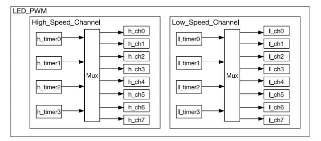
In total, there are 16 PWM channels available. These channels can be mapped to the different GPIO ports of the device, which are not engaged with other functions. Four high-speed timers control the high-speed channels, and another four control the low-speed channels. You can use different combinations of PWM frequencies and resolutions. Some common ones are listed below for your convenience.
| LEDC Clock Source | LEDC Output (PWM) Frequency | Highest Resolution |
|---|---|---|
| APB_CLK (80 MHz) | 1 kHz | 1/65536 (16 bit) |
| APB_CLK (80 MHz) | 5 kHz | 1/8192 (13 bit) |
| APB_CLK (80 MHz) | 10 kHz | 1/4096 (12 bit) |
| RTC8M_CLK (8 MHz) | 1 kHz | 1/4096 (12 bit) |
| RTC8M_CLK (8 MHz) | 8 kHz | 1/512 (9 bit) |
| REF_TICK (1 MHz) | 1 kHz | 1/512 (9 bit) |
It is also possible to fade the LED outputs using the LEDC controller’s hardware resource. Consequently, you may need some RTOS knowledge to effectively use this feature. Otherwise, you can use software techniques for this, although it can eat up some CPU cycles.
How to us a LED PWM?
The Circuit
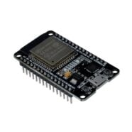
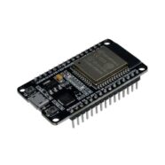
Your ESP32 devkit’s built-in LED can be used to demonstrate PWM. Otherwise, you can wire up a resistor and an LED on an empty GPIO port if your devkit doesn’t have one.
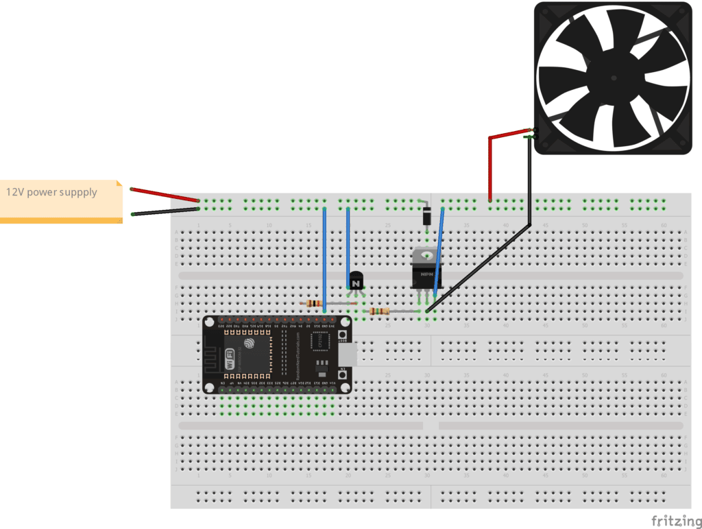
Get a small PC Fan, a 12V power supply, some transistors, and resistors for the fan speed controller. You can wire them up on a breadboard. You can use bipolar transistors or a MOSFET as a fan driver.
For BJT transistor Fan Driver
- 1 pc. TIP 31C
- 1pc. 2N3904
- 1pc resistor – 10k
- 1pc resistor – 150 ohms
- 1pc 1N4001 (Back-EMF protection)
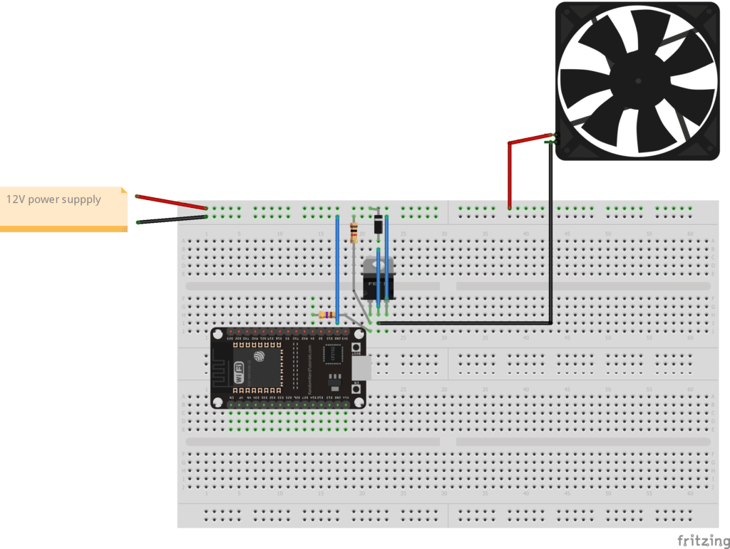
For FET FAN Driver
- 1 pc. IRFZ44N
- 1pc resistor – 470 (gate resistor)
- 1pc resistor – 10k (pull-down gate resistor)
- 1pc 1N4001 (Back-EMF protection)
BJT Transistor Type Fan Controller
FET Type Fan Controller
The Program
Before making an Arduino program for your ESP devices on the Arduino IDE, make sure you’ve read ESP32 on the Arduino IDE.
Introduce some definitions for the GPIO Pins, PWM channels, and the PWM resolution to use. After that, declare a constant variable MAX_DC for the maximum possible PWM duty cycle:
					#define LED1        2
#define FAN1        4
#define PWM_CH_LED  0
#define PWM_CH_FAN  1
#define PWM_RES     8
const int MAX_DC = (int)(pow(2, PWM_RES) - 1);
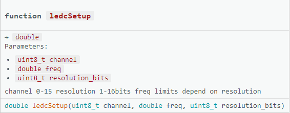
Next, initialize the LEDC module in the setup part of your Arduino code using the ledcSetup and ledcAttach Pin statements:
					void setup() {
  // put your setup code here, to run once:
  Serial.begin(115200);
  Serial.println("PWM Program");

  // PWM CH 0 (LED)
  // 5 kHz freq
  // 8 bit resolution
  // attached to GPIO 2
  ledcSetup(PWM_CH_LED, 5000, PWM_RES);
  ledcAttachPin(LED1, PWM_CH_LED);

  // PWM CH 1 (FAN)
  // 5 kHz freq
  // 8 bit resolution
  // attached to GPIO 4
  ledcSetup(PWM_CH_FAN, 5000, PWM_RES);
  ledcAttachPin(FAN1, PWM_CH_FAN);

  // kick start the FAN
  ledcWrite(PWM_CH_FAN, MAX_DC);
  delay(1000);

}
The code has an LED and a FAN part. Note that the FAN needs some initial “kick” to make it continue to turn without making it stall.
Here is the function prototype for ledcSetup()
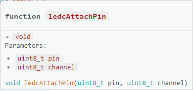
And here is the function prototype for ledcAttachPin:
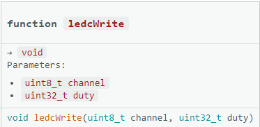
In the main loop, use the ledcWrite() function inside a for-loop to change the duty cycle of the PWM for both the LED and the FAN.
					void loop() {
  // put your main code here, to run repeatedly:
  Serial.println("Run Software Fader");

  uint8_t i;
  for(i=0;i<MAX_DC;i++)
  {
    ledcWrite(PWM_CH_LED, i);
    ledcWrite(PWM_CH_FAN, i);
    delay(10);
  }

}
Put a delay inside the for-loop so you can notice the PWM changes.
Here is the complete code:
					#define LED1        2
#define FAN1        4
#define PWM_CH_LED  0
#define PWM_CH_FAN  1
#define PWM_RES     8
const int MAX_DC = (int)(pow(2, PWM_RES) - 1);

void setup() {
  // put your setup code here, to run once:
  Serial.begin(115200);
  Serial.println("PWM Program");

  // PWM CH 0 (LED)
  // 5 kHz freq
  // 8 bit resolution
  // attached to GPIO 2
  ledcSetup(PWM_CH_LED, 5000, PWM_RES);
  ledcAttachPin(LED1, PWM_CH_LED);

  // PWM CH 1 (FAN)
  // 5 kHz freq
  // 8 bit resolution
  // attached to GPIO 4
  ledcSetup(PWM_CH_FAN, 5000, PWM_RES);
  ledcAttachPin(FAN1, PWM_CH_FAN);

  // kick start the FAN
  ledcWrite(PWM_CH_FAN, MAX_DC);
  delay(1000);

}

void loop() {
  // put your main code here, to run repeatedly:
  Serial.println("Run Software Fader");

  uint8_t i;
  for(i=0;i<MAX_DC;i++)
  {
    ledcWrite(PWM_CH_LED, i);
    ledcWrite(PWM_CH_FAN, i);
    delay(10);
  }

}
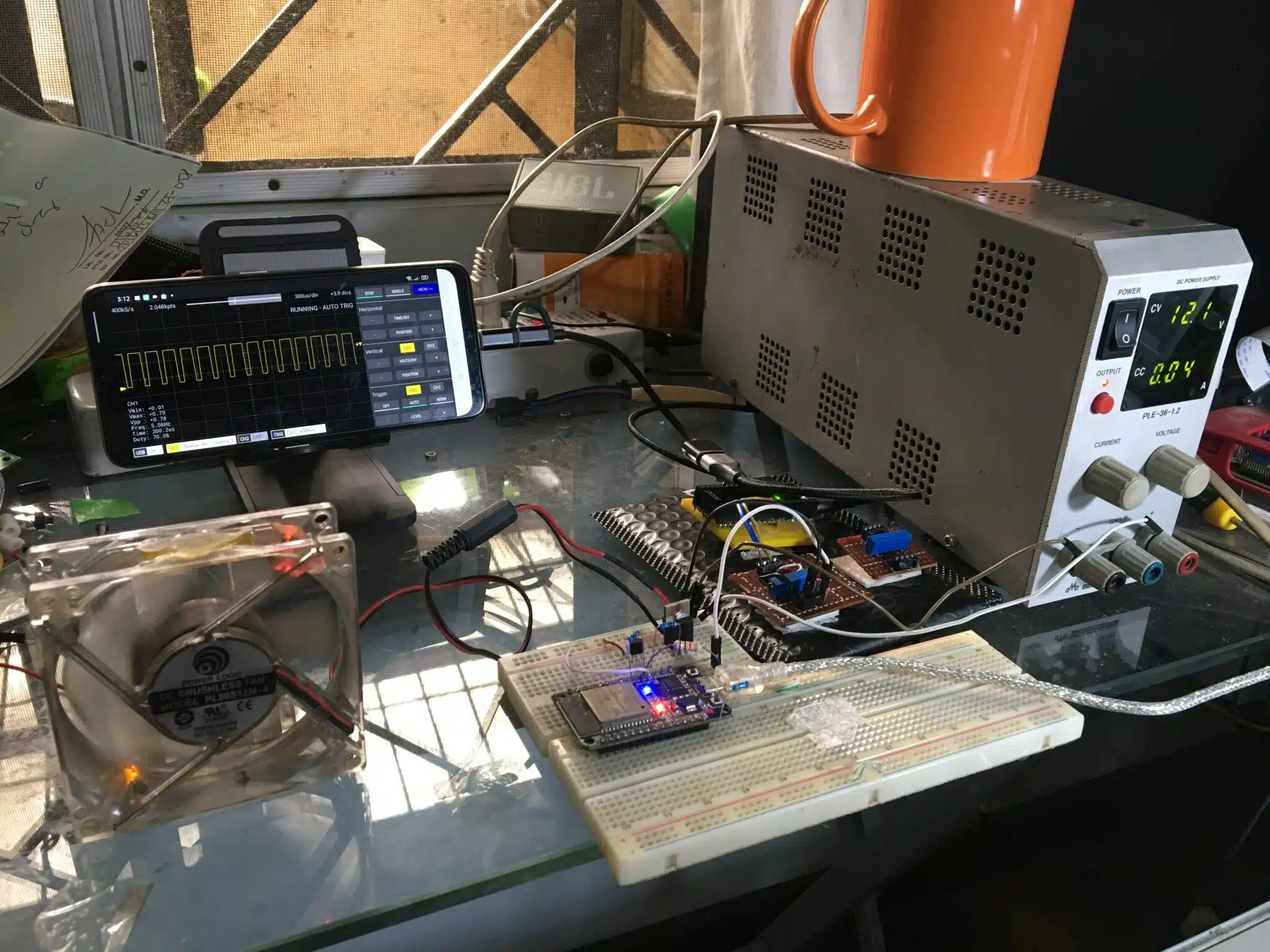
Below is a video of the circuit in action.
Note that you will see the PWM waveform change in time with the fading of the LED and turning of the FAN.
Find out more ESP32 devices and accessories that you can buy at Phipps Electronics: