Would you like to increase the current capacity of your power supply circuit? Not sure how to implement this? Read the rest of the article to find out.
Introduction
Power supply circuits are a good way to learn about electronics. They have different circuit configurations that make you explore things. Along with this, you learn new parts from different manufacturers. Consequently, you can always upgrade your power supply circuit when a need arises.
Increasing the current (or power) capacity of your power supply is a good place to start your upgrades. For example, if you’ve built a 1-ampere variable power supply, you could only use this for small hobby projects. You wouldn’t be able to use this for power circuits or motor-driven applications.
Fortunately, there is a way to upgrade your power supply circuit. You may need to replace some components though, as you’ll see later. You may also need to add a pass transistor to effectively increase the current capacity of your circuit.
Power Supply Blocks
In the previous article, the blocks of a basic linear power supply were discussed. This includes the following:
- Step-Down Stage
- Rectification Stage
- Filtering Stage
- Regulation Stage
- The Load
First, it’s wise to design your power supply with future upgrades in mind. Consider buying a more expensive Step-Down transformer with a higher current capacity. For example, if you’re just working on sub-1-ampere projects for now, you can already buy a 3-ampere transformer instead of limiting yourself to a 1-ampere transformer.
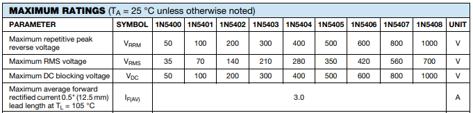
The same goes true for your Rectification stage. There are 3-ampere rectifier diodes available that you can use instead of using 1-ampere limited diodes. Make sure that you don’t exceed the Reverse Peak Voltage of your diode by having this value higher than the peak voltage your transformer can generate. See the chart below.
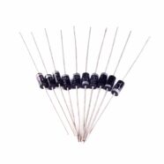
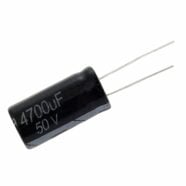
Your filtering stage is composed of a bulk filter capacitor. The size and capacitance of this capacitor can be increased. Increase its capacitance directly proportional to your targeted maximum current flow. A good formula to use is:
Capacitance = Maximum Current / (full-wave rect freq * Voltage ripple)
Where:
Capacitance is in Farrad
Maximum Current is the max current draw of your power supply depending on your load.
Full-wave rect freq is 2 x AC freq. If you have a 60Hz AC line then this equals to 120Hz.
Voltage ripple is your allowed ripple voltage. See the diagram below:
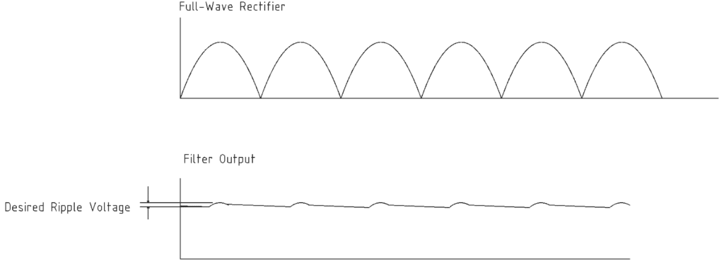
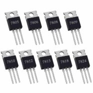
It’s important to note that the regulation stage usually has a regulator chip installed. The 78XX series of voltage regulator chips usually need 2 to 3V of voltage drop across them. This means your ripple voltage should be substantial enough to satisfy this value.
You may need the Voltage Peak value to complete the computation. Voltage peak is the root mean square multiplied by your transformer voltage value. If you have a 12V transformer, this equals (square root of 2) x 12V = 1.414 x 12V = 16.97 V.
For example, a 1V voltage ripple is allowed to happen so that a practical real-world capacitance value can be achieved. With a maximum load current of 3A:
C = 3A / 120 Hz (1V)
= 25000 uF
Use 27,000 uF or greater value.
If you only want a 0.5V voltage ripple:
C = C = 3A / 120 Hz (0.5V)
= 50,000 uF
Use 50,000 uF or greater value.
The Working Voltage of the capacitor can be made far above the transformer’s peak voltage.
WV of capacitor = 25V
The 2 to 3V voltage drop across the 7812 voltage regulator is satisfied through:
V input min = Vreg + 3V drop = 12V + 3V = 15V
For the 1V ripple:
V input max = 16.97V – 1V = 15.97V
For the 0.5V ripple:
V input max = 16.97V – 0.5V = 16.47V
Adding a Pass Transistor
The 78XX voltage regulator usually cannot handle currents in excess of 1 A. If you are going to use your power supply to supply 3A max, use a pass transistor for this. Pass transistors increase the current output of any regulated voltage output. Here is a simple example of a simple pass transistor configuration taken from a 7812 datasheet:
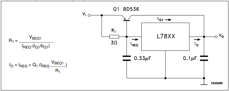
The pass transistor used here is a BD536. The BD356 has a maximum (absolute max) collector current of 8A. Make sure to connect a large heatsink for large collector currents and stay well below the maximum value.
As you can see, a resistor R1 is used to divert a part of the output current to the voltage regulator IC. The regulator’s current is the sum of Vbe/3 ohms plus the base current of Q1. The base current of Q1 is computed with its collector current divided by its Beta. Transistor Q1 may not conduct if the load demands are small, thereby letting the regulator IC supply all the current. This case is especially true if Ireg x R1 does not meet the Vbe needed to turn on transistor Q1.
Consequently, if you’re going to use a different pass transistor, verify the Beta and Vbe at different collector currents to achieve more reliable computations.
There are a wide variety of power components and blocks that you can use for your projects at Phipps Electronics: