Understand the function, uses, and different kinds of Inductive Proximity Sensor Switches here.
Introduction
Inductive proximity sensor switches are widely used in the manufacturing and automation industry. They’re used in factories, 3D printers, robotics, automotive assembly, conveyor systems, etc. Their main use is to detect metal objects (usually while in motion) at a close distance, acting like a non-contact limit switch. With this, a signal is sent to the controller to perform the necessary action.
It’s important to note that these switches cannot determine the actual distance from the detected metal object. Instead, inductive proximity sensor switches only activate when the metallic body approaches an approximately defined distance.
Basic Construction and Operation
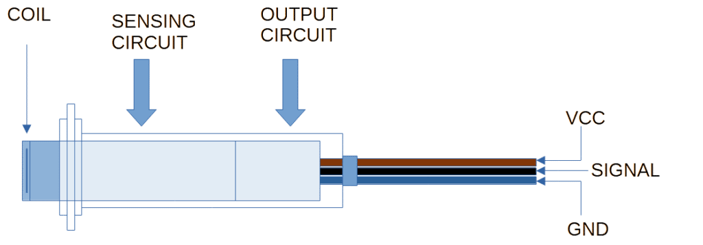
Inductive proximity switches are usually made internally with three parts: a coil, a sensing, and an output circuit.
An inductive coil is activated by the sensing circuit. The sensing circuit is usually composed of an oscillator and a trigger. Because of the inductive nature of the coil, a metal object coming near it can create a field disturbance. This disturbance (in proportion to the distance of the metal object to the coil) should be sufficient to activate the trigger circuit which also activates the output.
Different Kinds of Inductive Proximity Sensor Switches
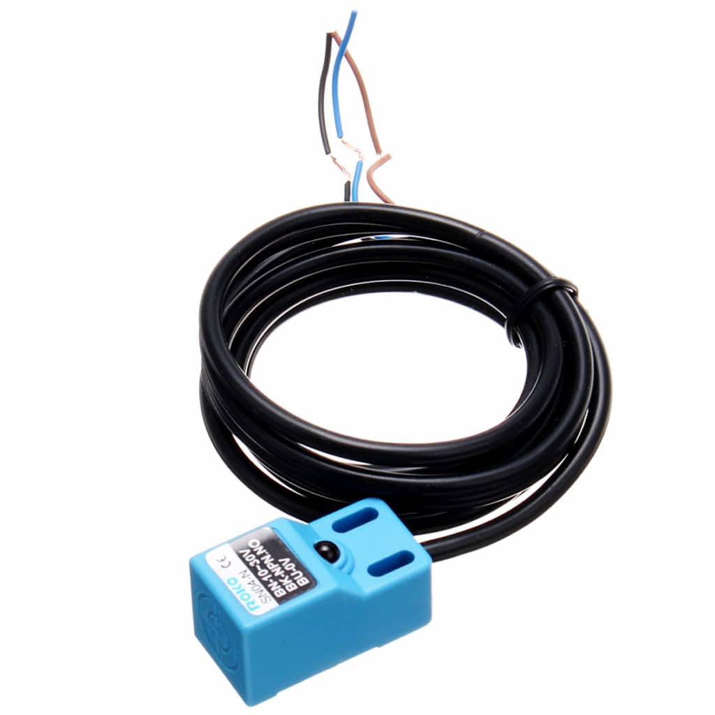
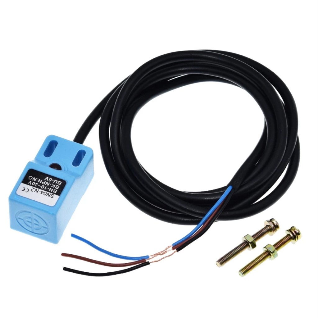
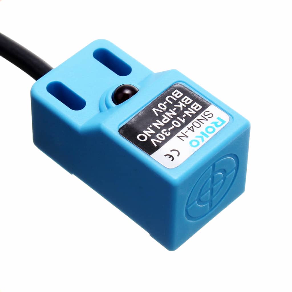
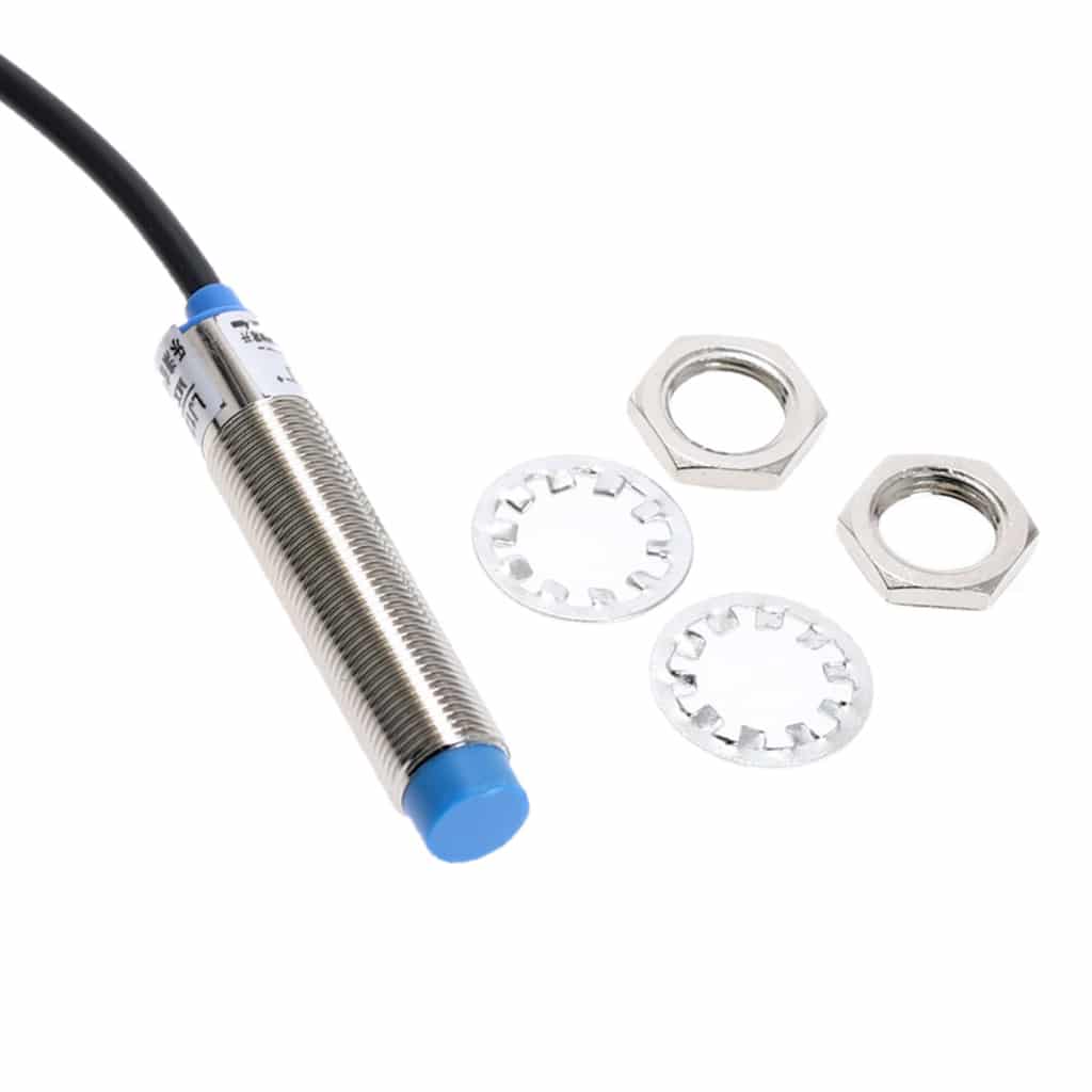
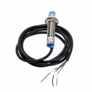
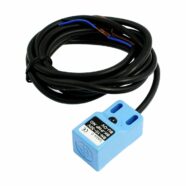
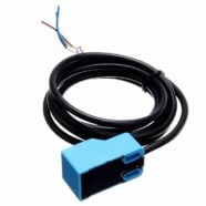
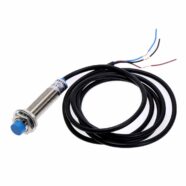
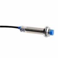
You may encounter different kinds of inductive proximity switches. Some have a round metal casing while others have a rectangular plastic PVC type.
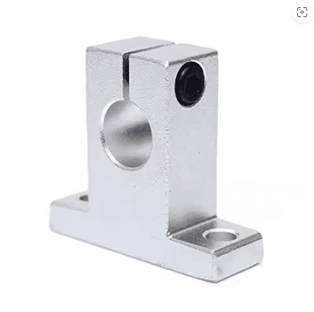
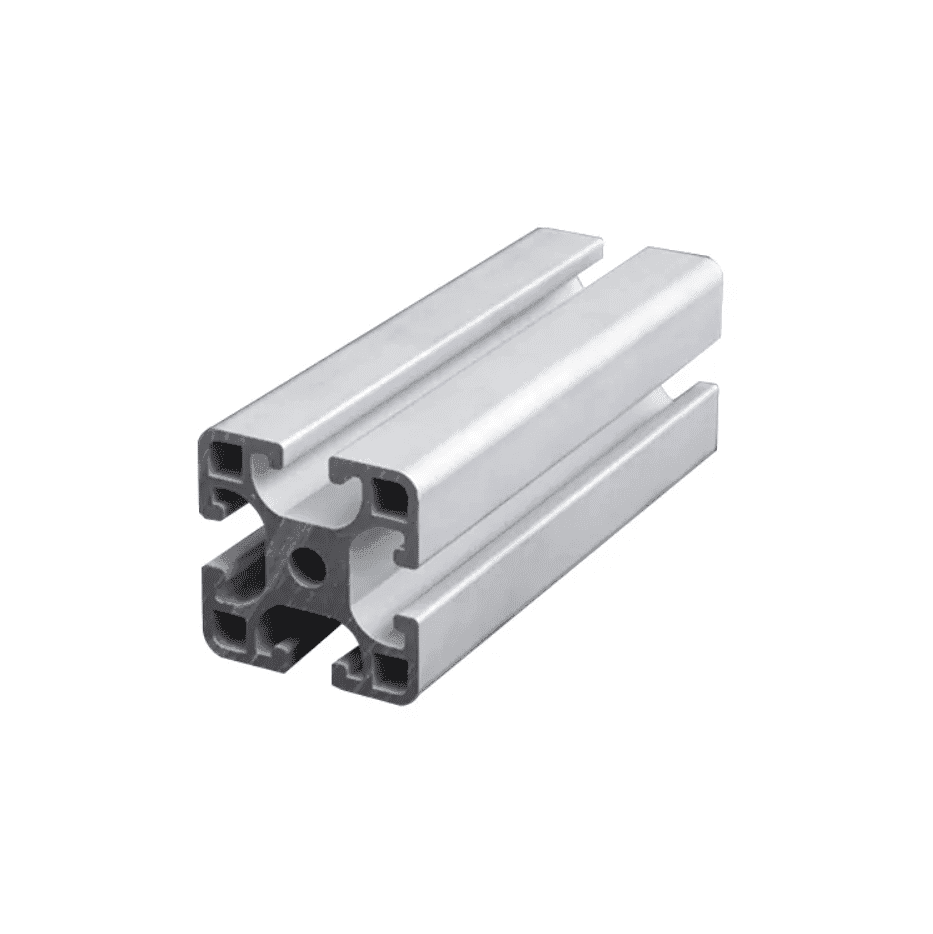
You can attach an inductive proximity sensor switch with a metal rounded chassis to a linear rail rod clamp to secure it. The rod clamp can then align or attach to an aluminum extrusion. When an incoming metal fixture or object comes near the rod clamp, the sensor activates to alarm the controller so that the appropriate actions can be taken.
Alternatively, you can attach a sensor with a rectangular PVC type case to any flat surface with drilled holes for mounting with screws like machine frames, robotic arms, etc.
Output Configurations
The sensors can have different kinds of output configurations to fulfill the needs of your load, controller, or even a relay input. Note that a sensor can be Normally Open (NO) or Normally Closed (NC) and it depends on the default signal at the base of the transistor.
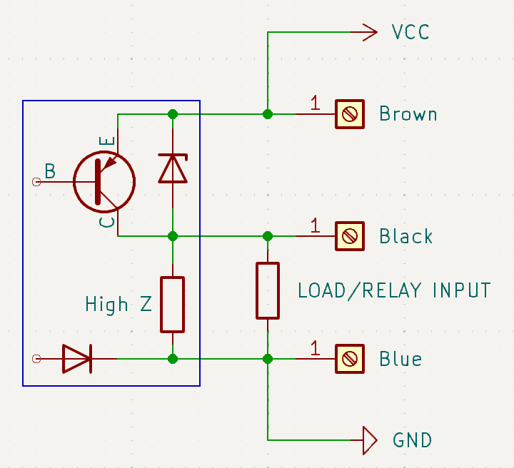
NPN - Normally Open (NO) or Normally Closed (NC)
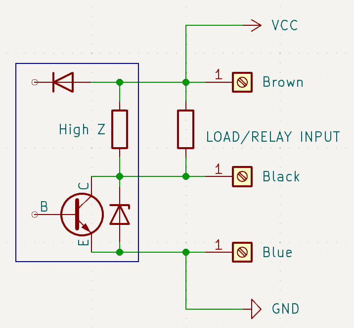
An NPN is an open-collector-type configuraton using an NPN transistor. The load is ideally connected between VCC and the Signal Terminal. This configuration means that when the sensor switch is OPEN, one side of your load is connected to VCC while the other side is left floating. When the SENSOR switch is closed, one side of your load is connected to VCC while the other side is grounded. This is a good configuration if you don’t want your load always grounded, instead, connected to VCC. You must ensure though that each device’s voltages and current ratings satisfy your setup.
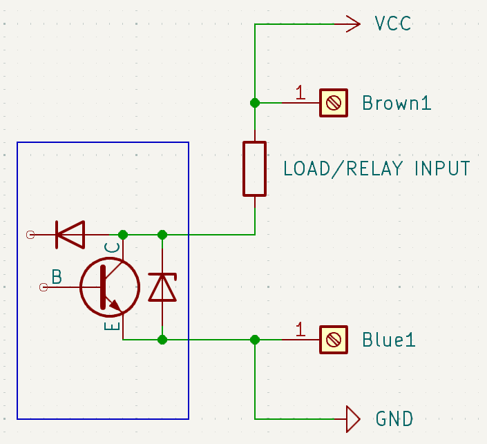
PNP - Normally Open (NO) or Normally Closed (NC)
A PNP is an open-collector-type configuration using a PNP transistor. The load is ideally connected between the Signal Terminal and Ground. This configuration means that when the sensor switch is OPEN, one side of your load is connected to the Signal Terminal while the other side is Grounded. When the SENSOR switch is closed, one side of your load is connected to VCC while the other side is grounded. This is a good configuration if you want your load always grounded. You must ensure though that each device’s voltages and current ratings satisfy your setup.
Two Wire - Normally Open (NO) and Normally Closed (NC)
Additionally, there is also the two-wire output configuration for the proximity sensor. In this configuration, you can connect your load in series with your sensor and power supply. You must ensure though that each device’s voltages and current ratings satisfy your setup. See the diagram above where the load is connected to the positive supply and the positive terminal of the sensor. The negative terminal of the sensor is grounded.