In this tutorial, we will learn about the KY-035 module, what is a Hall-effect switch and we will build a simple project to sense magnetic fields using the KY-035 with an Arduino.
Magnetic Analog Hall Sensor KY-035
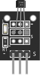
The KY-035 Module will be our main component for this tutorial. This module has a 49E Hall-effect switch IC in a TO-92 package and is mounted on a breakout board with an LED and resistor. Figure 1 shows the module as seen in fritzing.
Figure 1: KY-035 Magnetic Hall Sensor
Pin Out
The KY-035 module has three pins.
Pin
Description
(-)
GND
Middle Pin
+5V
S
Signal
What is a Hall-Effect Sensor 49E
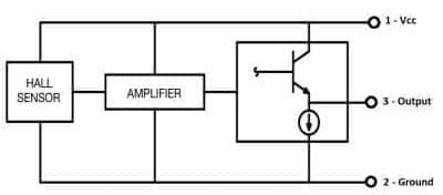
The Hall-Effect Sensor Analog 49E can detect a magnetic field’s magnetic pole and relative strength. In the case of our module, it sends an analog signal whenever it senses a magnetic field nearby. If no magnetic field exists, analog signal is half of the Vcc. Figure 2 shows the Block Diagram of the IC taken from its datasheet.
Figure 2: Block Diagram
Project - Arduino Magnetic Field Detector
After learning about the KY-035 module and the 49E IC, it is now time to build a project using the module. Our project will activate the built-in LED of an Arduino Uno when there is a magnetic field near the KY-035 module.
Components
For this project, we need the following components:
Arduino Uno board (1 pc.)
KY-035 Magnetic Hall Sensor (1 pc.)
Jumper wires
Wiring Diagram
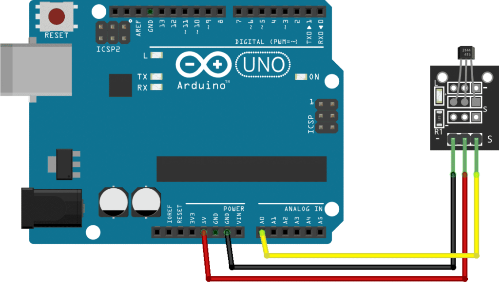
Figure 2 shows the connection between the Arduino Uno and the KY-035 Magnetic Hall Sensor.
Figure 3: Connection Diagram
The KY-035 module pins are connected to the Arduino Uno board as follows:
Component Pin
UNO Board Pin
(-)
GND
Middle Pin
+5V
S
A0
Code
Below is the Arduino sketch for our project. I have added comments to explain important parts of the code. Save the code as KY-035.ino and upload it to your Arduino board.
					// Arduino and KY-035 module
void setup ()
{
Serial.begin(9600); // initialize serial
}
void loop ()
{
Serial.print(analogRead(A0)); // display analog and digital values to serial
}
Project Test
Apply power to your Arduino Uno board and open the Serial Monitor. The analog value sent by the module will be displayed on the serial monitor. A value from 0~128 means a negative magnetic polarity, while a value from 129~255 means a positive magnetic polarity.
SUBSCRIBE FOR NEW POST ALERTS
Subscribe to be the first to know when we publish a new article!