This blog is part 2 of the ATtiny85 Sleep Modes Tutorial. Discover how to code for the Sleep Modes.
Introduction
ATtiny85 Sleep Modes Tutorial Part 1 introduced you to the different ATtiny85 sleep modes, the mode’s characteristics, and wake-up sources. Here, you’ll learn how to do basic coding for these sleep modes.
General Sleep Mode Coding
It’s relatively easy to do Arduino coding for the sleep modes. First, you need to ready the sleep mode you’re going to use (Idle, ADC Noise Reduction, or Power Down Mode) through the command below. This is not the actual sleep code yet to sleep the CPU, but you are declaring or setting up what kind it is.
					  // Set Sleep Mode
  set_sleep_mode(SLEEP_MODE_PWR_DOWN);
You can find the available sleep mode items here which are simple definitions.
					#define SLEEP_MODE_IDLE (0x00<<3)
#define SLEEP_MODE_ADC (0x01<<3)
#define SLEEP_MODE_PWR_DOWN (0x02<<3)
Note that you may encounter wake-up issues when using Ilde mode since Arduino uses the millis() function in the background, which uses the Timer0 Interrupt by default. This process may inadvertently wake-up your MCU from Idle.
Next, you can set up the wake-up sources for your chosen Sleep Mode. These sources can be a valid interrupt, a watchdog timer, or others (please refer to ATtiny85 Sleep Modes Tutorial Part 1). The statement below uses a Pin Change Interrupt as a wake up source.
					  // Set Change on Interrupt Pin
  attachPCINT(digitalPinToPinChangeInterrupt(BUTTON), PinChangeDet, FALLING);
Alternatively, here is code to set up a Watchdog Timer as a wake-up source that can wake up the MCU every second.
					    // Set Watchdog Timer to trigger every 1 second
    WDTCR |= (1 << WDCE) | (1 << WDE); // Enable Watchdog Timer configuration mode
    WDTCR = (1 << WDP2) | (1 << WDP1) | (1 << WDP0); // Set timeout to 1 second
    WDTCR |= (1 << WDIE); // Enable Watchdog Timer
If you need to enable global interrupts for your wake-up source, you may do so.
sei(); // Enable global interrupts
Next, upon going to sleep, enable the sleep functionality on the registers of the MCU through the statement below.
					  // Enable Sleep
  sleep_enable();
Then, do the actual sleeping through the command:
					  // Do the actual Sleeping zzz..
  sleep_cpu();
When the MCU sleeps, it halts the CPU from running code. It then waits for a system resource to wake it up. When it wakes up, it will continue to run code after the sleep_cpu() statement. At this time, you can disable sleep functionality temporarily (re-enabling it later) using the sleep_disable() command. You can run the rest of your code now.
					// continue from sleep here...

// disarm sleep
sleep_disable();
A Crude Sleep Mode Test
Below is a simple setup to demonstrate sleep. The setup only consists of the ATtiny85 MCU, a USBTiny programmer, a 1K ohm resistor, a 0.1uF filter cap, an LED, some jumpers, a breadboard, and an Analog Multimeter.
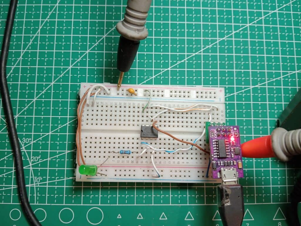
The code below demonstrates a crude implementation of the general sleep code. An LED lights up 3 times before going to sleep Zzzz… This demo code never wakes up from sleep.
					#include <avr/sleep.h>

#define LED PB3

void setup() {
  // put your setup code here, to run once:
  pinMode(LED, OUTPUT);

  // Sleep Mode
  set_sleep_mode(SLEEP_MODE_PWR_DOWN);

}

void loop() {
  // put your main code here, to run repeatedly:

  // run code
  digitalWrite(LED, HIGH);
  delay(1000);
  digitalWrite(LED, LOW);
  delay(1000);
  digitalWrite(LED, HIGH);
  delay(1000);
  digitalWrite(LED, LOW);
  delay(1000);
  digitalWrite(LED, HIGH);
  delay(1000);
  digitalWrite(LED, LOW);
  delay(1000);

  // Enable Sleep
  sleep_enable();

  // Do the actual Sleeping zzz..
  sleep_cpu();

  // continue from sleep here...

  // disarm sleep
  sleep_disable();

}
The video demo below will give you an idea of the power saving in your chosen sleep mode (e.g. Power Down Mode) with default settings (using 8MHz internal Oscillator, no other disabled peripherals, etc.). The ammeter is set to 25mA, which resets the setup. When the ATtiny85 runs, turning ON and OFF an LED, it garners around less than 15mA of current. When the sleep mode kicks in, the ammeter scale is scaled down to 2.5mA max for a more precise reading. The resulting current should be around 300uA.
In actuality, this code is useless because, in sleep, you do not execute any code. The usefulness of the sleep function comes in the sleep-wakeup cycle. In several cases, you don’t really need your MCU running code all the time. With this, you should know when is the best time to sleep and wake up your MCU in order to save power.
Wake Up with User Intervention (Button Press)
Here is an example of a sleep mode woken up by user intervention. The setup consists of a mini buzzer along with a tact switch. This setup can be used as a door melody chime. When one enters a room, a switch or a sensor activates, waking the MCU to sound a chime. Thereafter, the MCU sleeps again to conserve power, waiting for another user intervention.
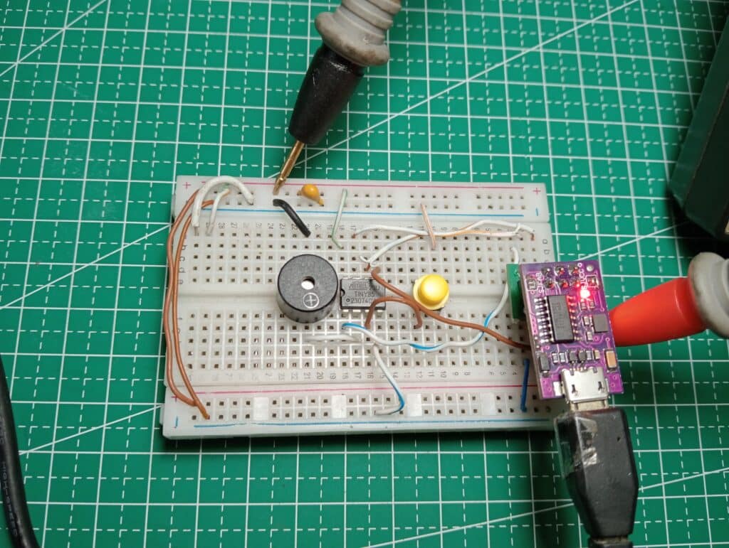
The code for this setup follows General Sleep Mode Coding. For simplicity, the interrupt code uses the Pin Change Interrupt library. You can add this library to your Arduino IDE by searching for it in the Libraries area. Don’t forget to include the library on your header file. Note that the Pin Change interrupt is one of the system resources that can wake up the MCU in Power Down Sleep Mode.
					#include <avr/sleep.h>
#include <PinChangeInterrupt.h>


#define BUZZER PB3
#define BUTTON PB4


void setup() {
  // put your setup code here, to run once:
  pinMode(BUTTON, INPUT_PULLUP);
  pinMode(BUZZER, OUTPUT);

  // Sleep Mode
  set_sleep_mode(SLEEP_MODE_PWR_DOWN);

  // Set Change on Interrupt Pin
  attachPCINT(digitalPinToPinChangeInterrupt(BUTTON), PinChangeDet, FALLING);

}

void loop() {
  // put your main code here, to run repeatedly:

  // Enable Sleep
  sleep_enable();

  // Sleep upon startup Zzzz..
  sleep_cpu();

  // Unsleep here... must wake-up on pin change interrupt

  // disarm sleep
  sleep_disable();

  // Door Melody Chime
  chime();

}

void PinChangeDet(void) {
  // do nothing... must wake up the MCU
}

void chime(void)
{
  byte i;
  for(i=0;i<10;i++)
  {
    digitalWrite(BUZZER, HIGH);
    delay(100);
    digitalWrite(BUZZER, LOW);
    delay(100);
  }
}
The Pin change Interrupt is set up through:
					  // Set Interrupt on Change Pin
  attachPCINT(digitalPinToPinChangeInterrupt(BUTTON), PinChangeDet, FALLING);
where BUTTON is the digital pin to attach this interrupt and PinChangeDet is the ISR function. The third parameter is the signal edge where the interrupt happens and could be FALLING, RISING, or a CHANGE in signal transition edge.
The program starts immediately in sleep mode, waiting for a Pin Change interrupt on Port PB4. When this happens, the system wakes up from sleep. Code should then run in the PinChangeDet() ISR function; however, code does not need to be written here. With this, the system continues to run the statements after the sleep_cpu() function, disarms sleep, and then proceeds to chime using the buzzer at port PB3. After this, the system rolls back to sleep mode again.
In the actual run, you’ll see the system running at about less than 20mA when activated through the button. When in sleep mode, the current goes down to about 300uA.
Periodic Wake Up Using a Watchdog Timer
There are times in your projects where you can’t have the user intervene to wake up your MCU. With this, you need a periodic wake up source. Using a Watchdog Timer to wake up your MCU from sleep mode is a very good technique to time an event or a sensor reading (through a system reset) and not keep your CPU running all the time. Consequently, using the WDT in Power Down Sleep mode as wakeup source is perfect since most of the clock sources are shutdown in Power Down sleep mode, and WDT has its own dedicated low power clock source.
Below is a barebones code for Power Down sleep mode, which is woken up by a watchdog timer every second. Every second, an LED is toggled on the WDT ISR.
					#include <avr/io.h>
#include <avr/interrupt.h>
#include <avr/sleep.h>
#include <avr/wdt.h>

void setup() {

    // Set Watchdog Timer to trigger every 1 second
    WDTCR |= (1 << WDCE) | (1 << WDE); // Enable Watchdog Timer configuration mode
    WDTCR = (1 << WDP2) | (1 << WDP1) | (1 << WDP0); // Set timeout to 1 second
    WDTCR |= (1 << WDIE); // Enable Watchdog Timer interrupt

    sei(); // Enable global interrupts

    // Set the sleep mode to power-down
    set_sleep_mode(SLEEP_MODE_PWR_DOWN);
}

ISR(WDT_vect) {
    // Watchdog Timer interrupt service routine (ISR)
    // This code runs every time the Watchdog Timer triggers
    // Example: Toggle an LED
    PORTB ^= (1 << PB3); // Toggle PB3

}

void loop() {
    // Put the MCU into sleep mode
    sleep_enable();
    sleep_cpu(); // Enter sleep mode

    // The MCU will continue here after waking up
    sleep_disable(); // Disable sleep mode

}
Application of the Periodic Watch Dog Timer Wake UP
Lorem ipsum dolor sit amet, consectetur adipiscing elit. Ut elit tellus, luctus nec ullamcorper mattis, pulvinar dapibus leo.