Are you curious about the workings and functionality of the ESP32-CAM? In this article, we’ll discuss this devkit in detail. Get ready to record photos and videos wirelessly using this compact tool.
Introduction
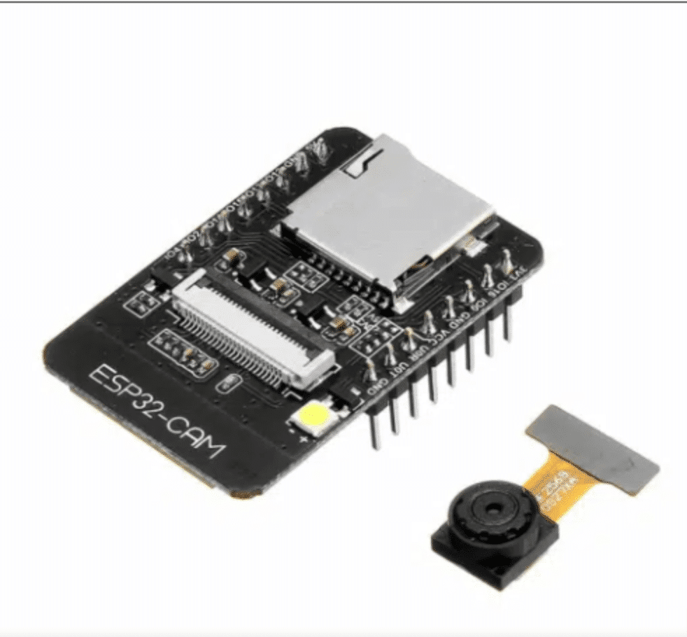
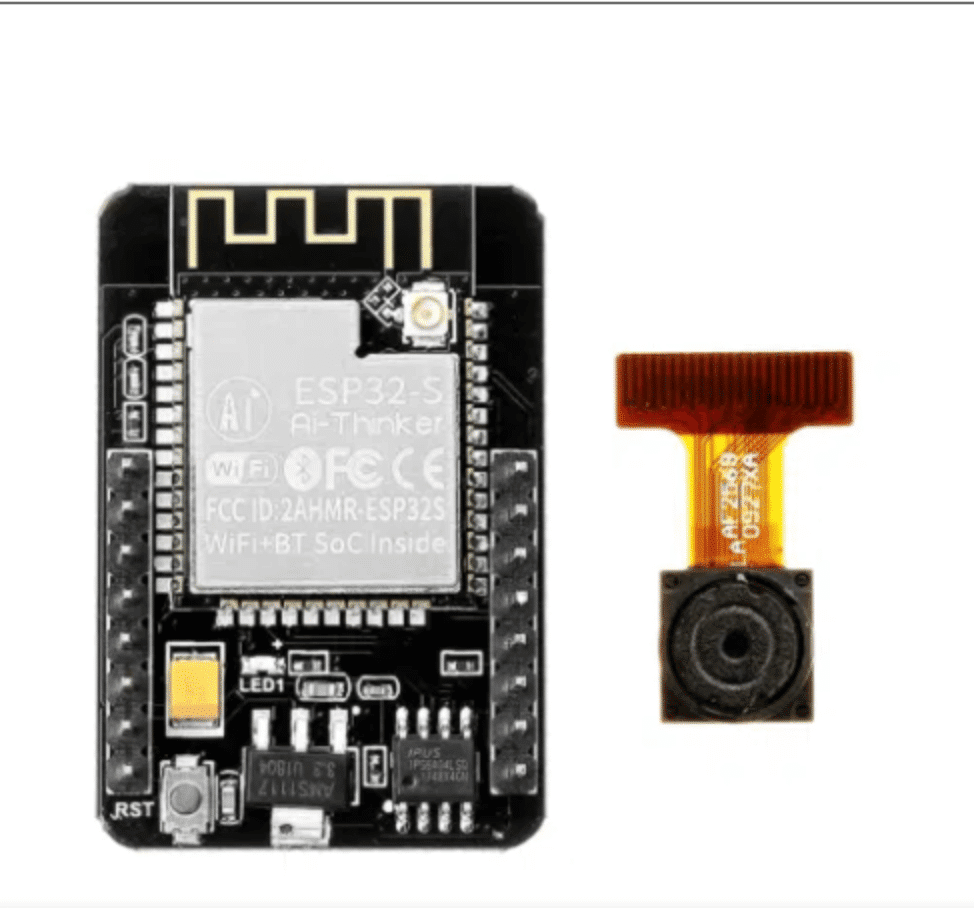
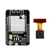
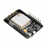
ESP32-CAM is a development kit from EsperessIF Systems. Its primary function is to be able to use a CMOS camera and connect it to a Wi-Fi network. It has other peripherals, such as an SD card slot and a 2.4GHz PCB antenna. The PCB antenna’s range can be extended by using a wired antenna.
There are several other modules developed by EspressIF. The company’s target is to make smart wireless modules for the Artificial Intelligence of things (AIoT).
Specifications
Operating voltage: 5V
Operating current: < 310mA MAX @ 5V
Camera models supported: OV2640 and OV7670
Package: DIP-16
SPI flash: 32Mbit (default)
RAM: 520KB internal 4M PSRAM
Bluetooth: 4.2BR/EDR and BLE
WiFi: 802.11 b/g/n/e/i
Interface: UART, SPI, I2C, PWM
IO ports: 9
Serial port range: 115200bps (default)
Image format: JPEG, BMP, Grayscale
Spectrum range: 2412 – 2484MHz
Antenna: On-board PCB, gain 2dBi
Dimensions: 27mm x 40.5mm x 4.5mm
Unpacking and first use
The ESP32-CAM is available through Phipps Electronics. It comes with an OV2640 camera module with a header attachment if you buy it. It does not come with a USB programming port, so you may have to buy a separate FDTI or a USB to UART converter to program it. A USB to UART module similar to this is also available through Phipp’s Electronics.
Programming the ES32-CAM
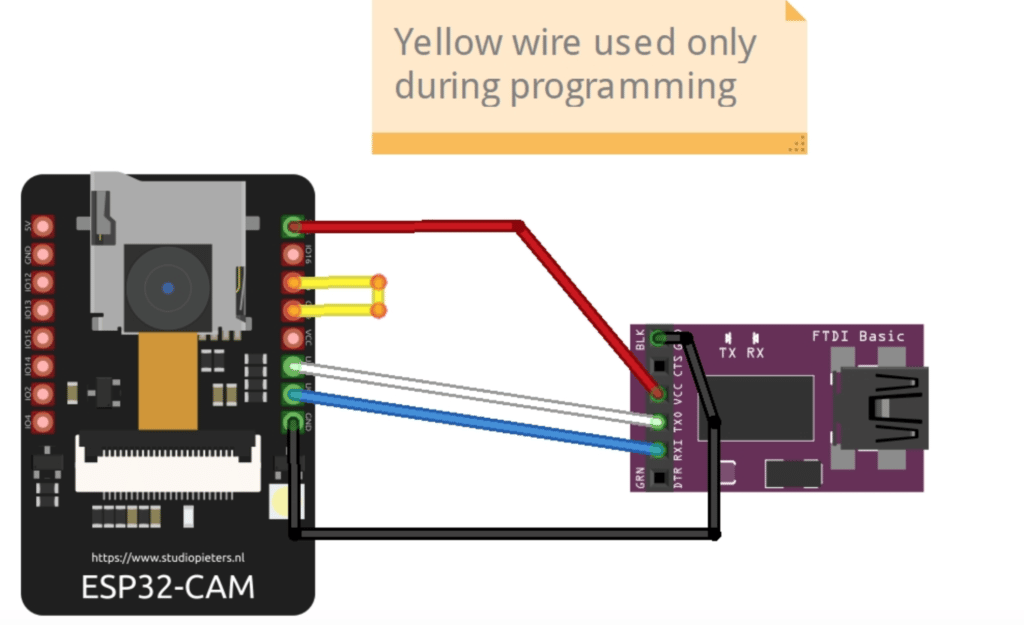
You’ll have to attach the FDTI programmer’s pins to the ESP32-CAM’s pins. The image below connects the ESP32-CAM’s TX pin to the RX pin of the programmer. The same goes for the RX pin of the EXP32 CAM, which goes to the TX pin of the programmer. ESP32-CAM is programmed with a power supply of 3.3V, so attach it to the 3.3V of the FTDI. Next, connect both their common ground with each other.
There is one last thing to do before programming, and it’s to connect GPIO pin 0 of ESP32 to the ground. During normal operations, remember to remove this connection.
Using The Arduino IDE to Program the ESP32-CAM
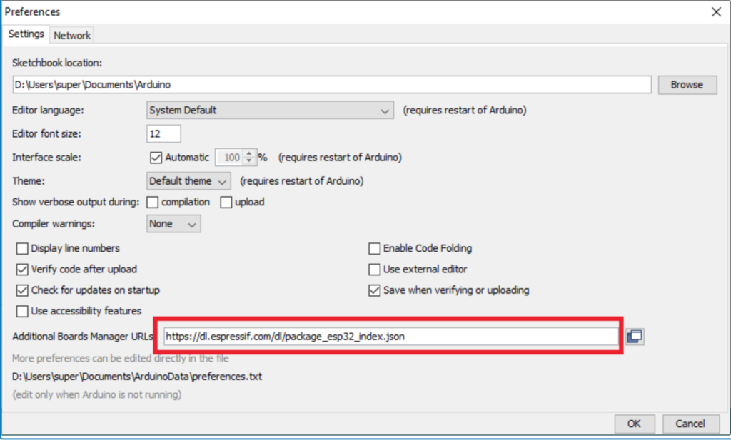
Like other non-Arduino boards, the ESP32-CAM needs an additional board manager URL to function correctly in the Arduino IDE. With this, activate it by going to File -> Preferences and input the URL below to the Additional Boards Manager URL text box as seen below:
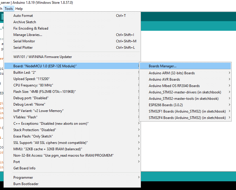
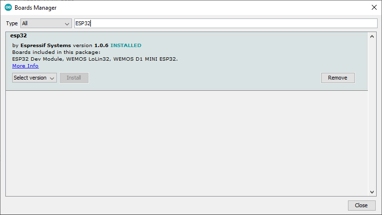
Once done, you’ll have to add the package to the Board Manager. Go to Tools -> Board -> Boards Manager… and search for ESP32.
Don’t forget to install it.
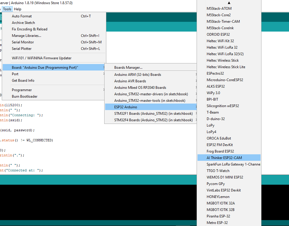
Next, you should have the ESP32-CAM available as a board. Go to Tool -> Board -> ESP32 Arduino -> then pick the AI Thinker ESP32-CAM (or the closest equivalent model to your board).
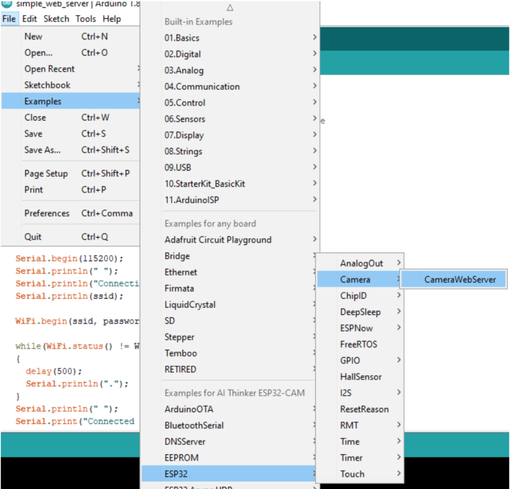
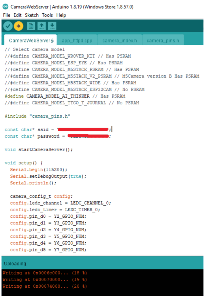
We can now start programming our ESP32-CAM with an example sketch. Go to File -> Examples -> ESP32 -> Camera -> and open the CameraWebServer example.
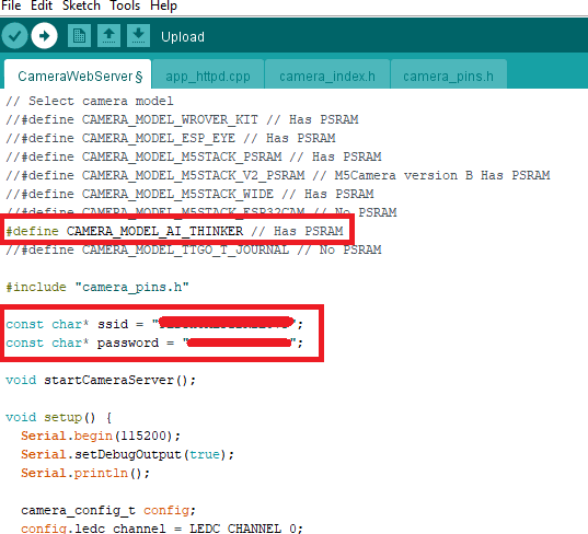
You’ll be greeted with different settings on the CameraWebserver program. First, select your camera model. Un-comment the #define for CAMER_MODEL_AI_THINKER. Remember to comment out the default value.
Second, place your own Wi-Fi SSID and password in the const char* SSID and password pointer string variables.
You can try compiling the sketch to see if you’ll have errors. Ideally, there should be none.
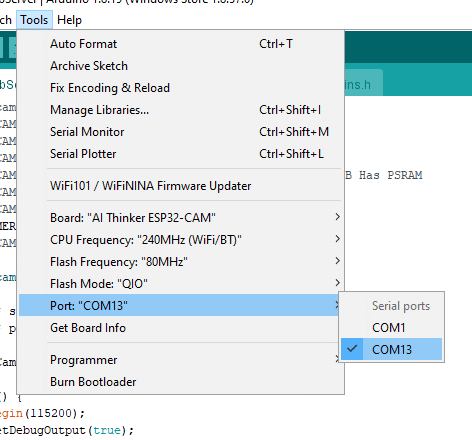
When you’re ready to upload the code to your ESP32-CAM, make sure that you have the correct serial port in use by clicking Tools -> Port.
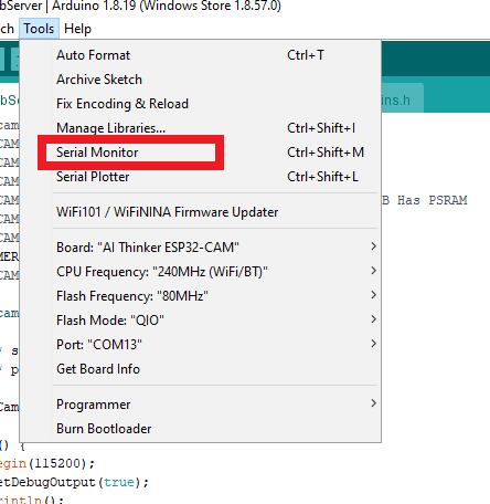
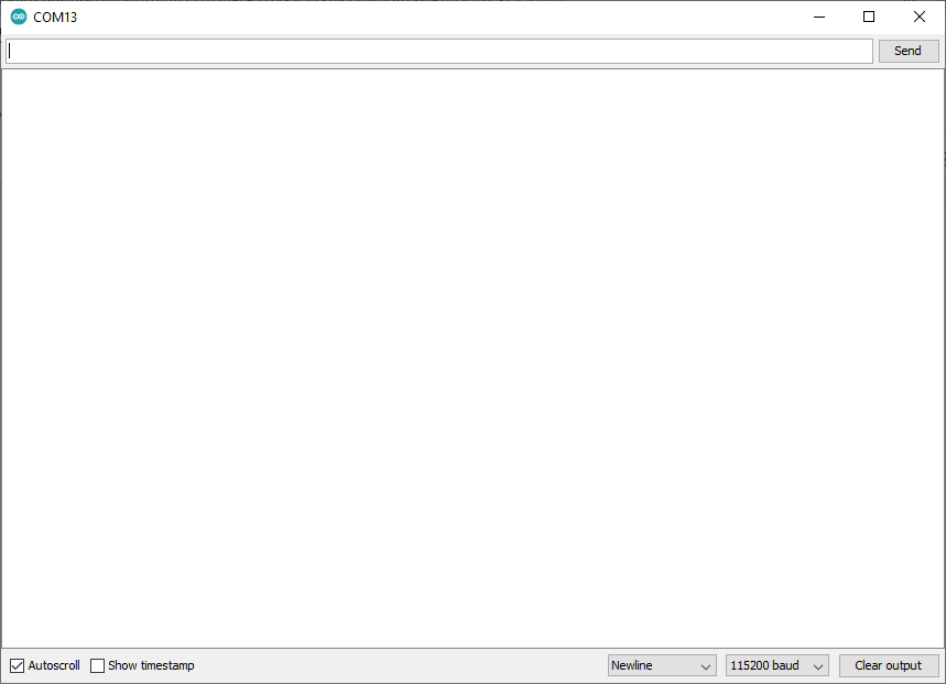
Also, open a Serial Monitor window and adjust its baud rate to 115200. This CameraWebServer example has lots of debug messages you need to follow.
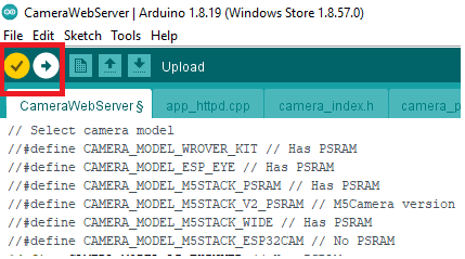
We’re ready to program our ESP32 CAM board. Hit the upload button to continue. If you’re seeing a “writing to flash percentage” running then it’s programming correctly.
After it’s finished, it may say it has reset through the RTS pin. Look now at your Serial Monitor Window. Your ESP32-CAM should be trying to connect to your Wi-Fi network. Take note of the Web Server IP address that it displays because you’ll be inputting it to a web browser.
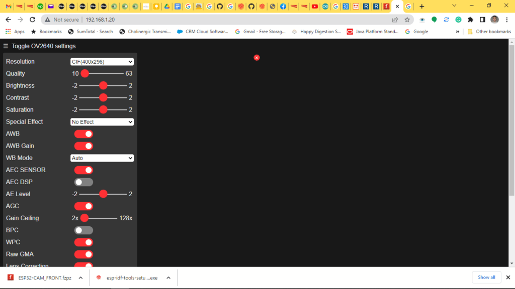
Open a web browser and input that IP address. You’ll see content similar below.
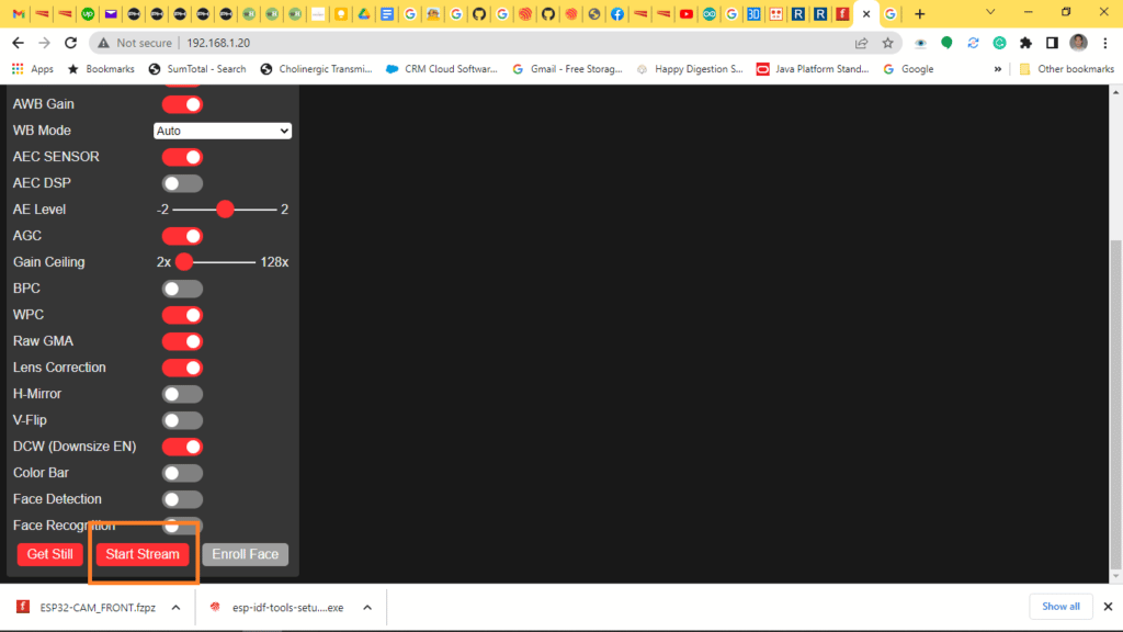
When you’re ready to stream your webcam video, click on Stream.
There you go. You’ve just started viewing webcam videos using the ESP32-CAM.
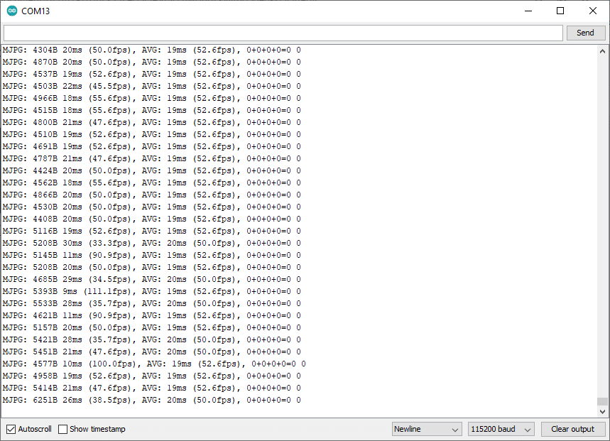
Now, go back to the serial monitor. You’ll see valuable details such as frame rates and other info.
Practical Tips For Using Your ESP32-CAM
Your ESP32-CAM should work fine, although you have to take a look at specific conditions. First is the power supply. When using WiFi, burst sequences can fluctuate your USB port power supply.
With the said condition, it’s better to supply the ESP32-CAM with its own power supply. Better yet, supply it through the 5V line so that its external voltage regulator will be the one to feed the 3.3V power needed by the ESP32 chip. With this setup, you’ll both have a cleaner supply and prevent brownout conditions by the ESP chip when hefty Wi-Fi burst sequences are executed.
The ESP32 CAM has a built-in white LED that you can use to light up dark views on your captures. Note that it’s connected to GPIO 4. With this, you’ll be able to control the light and turn it ON or OFF using digitalWrite statements. Note, however that it has an inverted logic. This means you need to write LOW to turn it ON and HIGH to turn it OFF.
The ESP32 CAM has a limited Wi-Fi range when using its PCB antenna. To extend its range, use a wired antenna. You can plug this antenna at the back side of the board where a single pin header is installed. Make sure to move the SMD resistor that connects to the PCB antenna so that the antenna now connects to the single pin header. Since this resistor is a zero ohm resistor, you can optionally bridge it out using solder leads.
Conclusion
The ESP32-CAM is a versatile wireless camera that can easily be set up. It can be programmed using a USB-to-UART converter using the Arduino IDE. It can work stand-alone and only needs the right amount of power to run smoothly. Once set up, download the CameraWebServer app to it, then use an internet browser to use this module as a web server camera.