#include <avr/sleep.h>
#include <PinChangeInterrupt.h>
#define BUZZER PB3
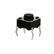
#define BUTTON PB4
void setup() {
// put your setup code here, to run once:
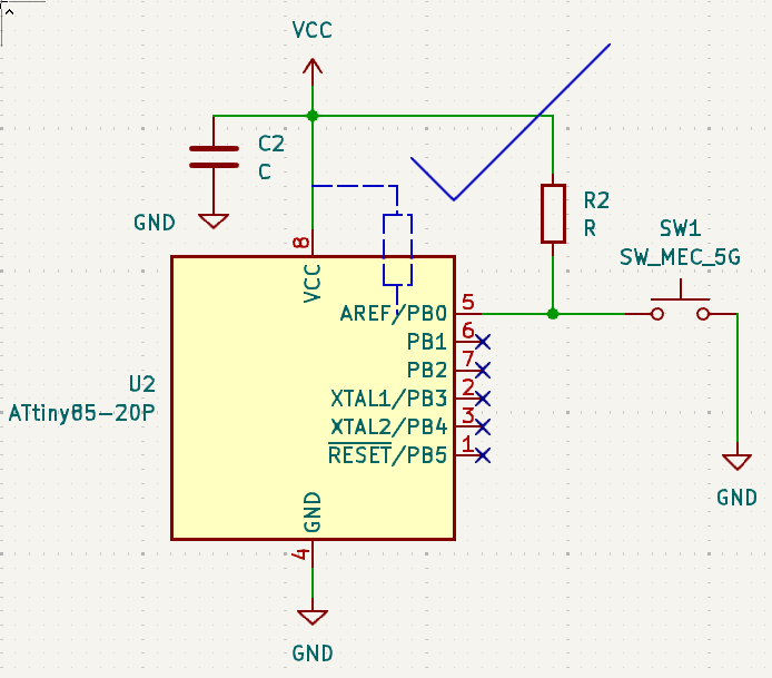
pinMode(BUTTON, INPUT_PULLUP);
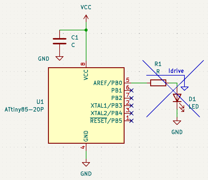
pinMode(BUZZER, OUTPUT);
// Turn OFF ADC to save power
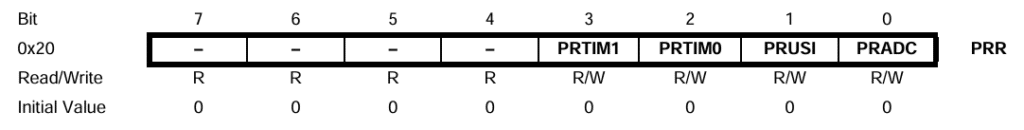
ADCSRA &= ~(1 << ADEN);
// Sleep Mode
set_sleep_mode(SLEEP_MODE_PWR_DOWN);
// Set Change on Interrupt Pin
attachPCINT(digitalPinToPinChangeInterrupt(BUTTON), PinChangeDet, FALLING);
}
void loop() {
// put your main code here, to run repeatedly:
// Enable Sleep
sleep_enable();
// Sleep upon startup Zzzz..
sleep_cpu();
// Unsleep here... must wake-up on pin change interrupt
sleep_disable();
// Door Melody Chime
chime();
}
void PinChangeDet(void) {
// do nothing... must wake up the MCU
}
void chime(void)
{
byte i;
for(i=0;i<10;i++)
{
digitalWrite(BUZZER, HIGH);
delay(100);
digitalWrite(BUZZER, LOW);
delay(100);
}
}