Introduction
In this tutorial, we will learn about the KY-016 module, what is an RGB LED and we will build a simple project to control the colour output of an RGB LED.
What is an RGB LED?
An RGB LED is simply 3 different coloured LED’s assembled in one package. The colour of each LED is Red, Green, and Blue hence the name. By varying the intensity of each of the 3 colours, we can produce other colours in the visible light spectrum.
The 3 Colour LED Module KY-016
The KY-016 Module will be our main component for this tutorial. This module has a 5mm RGB LED and 150-ohm resistors mounted on a breakout board to expose the R, G, B and Cathode pins of the LED. This component makes it very convenient for electronic enthusiasts like us to incorporate it into our projects. Figure 1 shows the module as seen in fritzing.
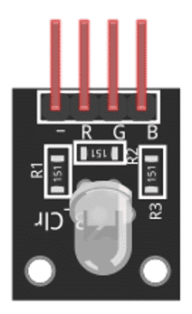
The KY-016 module has four pins.
| Pin | Description |
|---|---|
| R | Red colour component of the LED |
| G | Green colour component of the LED |
| B | Blue colour component of the LED |
| - | Cathode pin, to be connect to negative or ground |
Project - RGB LED Controller
After learning about RGB LED’s and the KY-016 module, it is now time to build a project using the module. Our project will take a potentiometer position as input to control the KY-016 module.
Project Components
For this project, we need the following components:
- Arduino Uno board (1 pc.)
- KY-016 RGB LED Module (1 pc.)
- 10-Kohm potentiometer (1 pc.)
- Jumper wires
Wiring Diagram
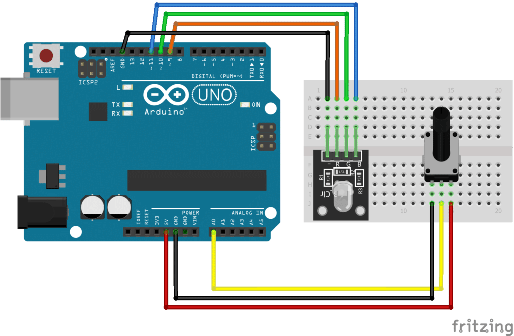
The KY-016 module pins and potentiometer pins are connected to the Arduino Uno board as follows:
| Component Pin | Arduino UNO Board Pin |
|---|---|
| KY-016 module Pin R | 9 |
| KY-016 module Pin G | 10 |
| KY-016 module Pin B | 11 |
| KY-016 module Pin (-) | GND |
| Potentiometer Pin Left | GND |
| Potentiometer Pin Middle | A0 |
| Potentiometer Pin Right | +5V |
The KY-016 module is controlled by sending analog values (PWM waves). In Arduino Uno, only pins 3, 5, 6, 9, 10, 11 can be used to output PWM. As seen in the connection diagram, we are using pins 9, 10, 11 for our module. Pin A0 will be input from the potentiometer.
The Code
					int vPot; // potentiometer value in range 0~1023
byte vRed = 0; // Red value in range 0~255
byte vGrn = 0; // Green value in range 0~255
byte vBlu = 0 // Blue value in range 0~255
void setup()
{
     // nothing to do here
}
void loop()
{
     // get potentiometer value from pin A0, map to range 0~765 and
     // save to variable vPot
     vPot = map(analogRead(A0), 0, 1023, 0, 765);
     // calculate Red, Green and Blue values from vPot value
     if(vPot > 510)  {
     vRed = 255;          // set Red value to 255 (max value)
     vGrn = 255;          // set Green value to 255 (max value)
     vBlu = vPot-510;     // subtract 510 from vPot to get Blue value
   }
   else if(vPot > 255) {
     vRed = 255;          // set Red value to 255 (max value)
     vGrn = vPot-255;     // subtract 255 from vPot to get Blue value
     vBlu = 0;            // set Blue value to zero (min value)
   }
   else {
     vRed = vPot;         // if vPot value is less than 255, vPot value will be assigned to Red
     vGrn = 0;            // set Green value to zero (min value)
     vBlu = 0;            // set Blue value to zero (min value)
   }
   // output RGB values to analog pins
   analogWrite(9, vRed);
   analogWrite(10, vGrn);
   analogWrite(11, vBlu);
}
Project Test
Move the potentiometer from minimum to maximum to adjust the colour output of the KY-016 module. By adjusting the potentiometer, we can vary the colour output of the RGB LED.