Have you sometimes wondered how those colourful household appliances create a cozy atmosphere by displaying hypnotizing and slow-transitioning LED effects? If so, read the rest of the article.
Introduction
LED dimming and lighting took everyone by storm in the 1980s. Before that, they were mainly used as an electronic component to signal to users that a device is ON or is in another working state. When the manufacturing process of LEDs became more efficient and reliable, LEDs’ use expanded exponentially, making them available to every home and establishment. Because of this, we’re seeing a variety of LEDs including multi-colored ones. The future can be seen to employ LED smart controllers for our everyday needs.
Since multi-color LEDs have a red, green, and blue component, coupling that with the capability to use PWM (Phase Width Modulation), different combinations of colors and brightness levels can be made. This brings up the topic of employing microcontrollers to control different kinds of LEDs. In this article, we’ll deal with different techniques to light up an RGB LED up to the point where you’ll be able to make soft color transition effects.
How to control LEDs
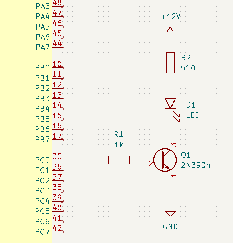
An LED’s brightness level can be controlled primarily by current. LEDs are current-driven devices and they have stayed like that throughout the years. Different LEDs require different amounts of power and this power is proportional to the brightness they emit. To control higher-powered LEDs, you’ll need a transistor to amplify their output power. BJTs and FETs are widely employed as power drivers for LEDs with FETs having the advantage of delivering power more efficiently.
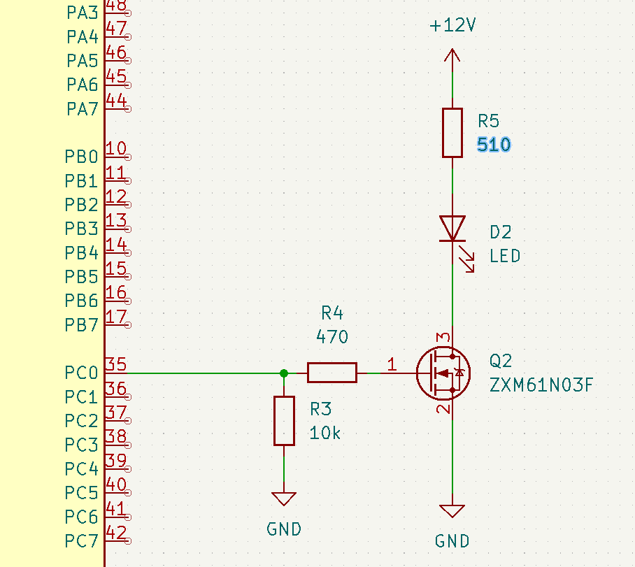
A FET-driven LED connected to an MCU
BJTs and Mosfets are not the only ones that can drive LEDs, similarly custom LED driver chips have been built for this application. Semiconductor companies have created different kinds of LED drivers and you can choose from a lot of them. Consider this RGB LED driver offered by Texas Instruments and Kinetic Technologies.
For low-power applications or just for educational or demonstrational needs, no driver is needed. The next part will focus more on how to play with different colors on an RGB LED.
How to Change and Combine Colours
To start, you’ll have to know how to use PWM and duty cycles on your MCU. You can find more information regarding PWM on an MCU here. By varying the duty cycle of your LEDs, you can achieve different brightness levels. Couple this feature with a multi-colored RGB led and you’ll be able to create a wide spectrum of different colors. Phipps Electronics offers different kinds of RGB LEDs using different configurations:
- Common Cathode RGB LED (Clear lens type)
- Common Anode RGB LED (Clear lens type)
- Common Cathode RGB LED (Diffused type)
- Lilypad RGB LED module
Fortunately, on an Arduino, you don’t have to mess up with all the technical details of PWM. It’s already implemented in a function as analogWrite(Pin, value), where value is an 8-bit value from 0 – 255 representing a 0% – 100% duty cycle.
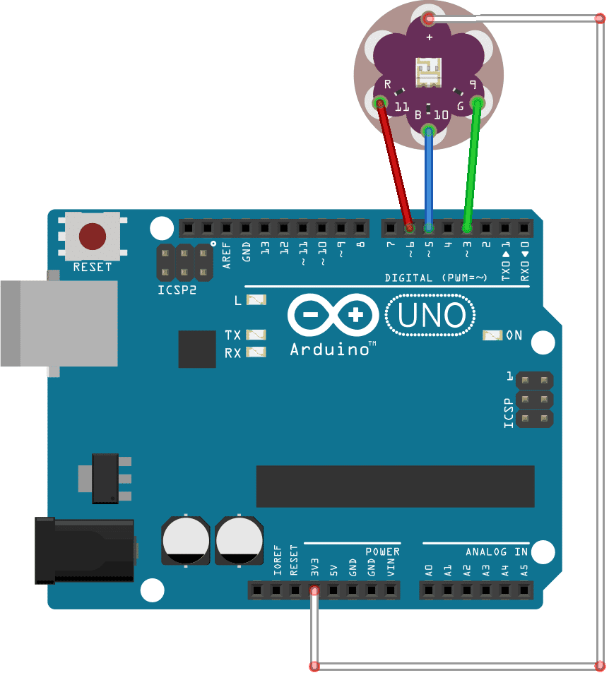
On an Arduino UNO try to wire up this Lilypad module. Choose the PWM terminals on your UNO (marked with ~), then get ready to start coding on the next part.
Making a Sample Code for Slow Transitioning Colours
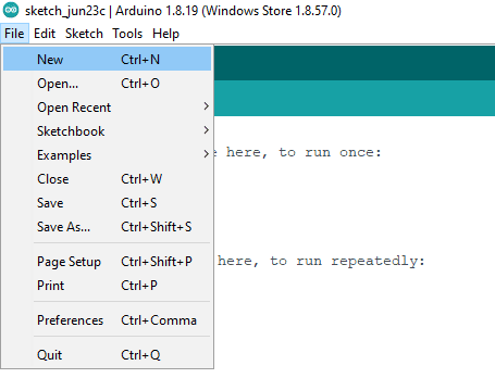
Open your Arduino IDE and start programming! Create a new sketch by clicking File->New:
Next, type in a couple of defines to relate the pins of your UNO to your colours
					#define RED   6
#define GREEN 5
#define BLUE  3
Then type in the setup code to define your pins as OUTPUTs
					void setup() {
  // put your setup code here, to run once:
  pinMode(RED, OUTPUT);
  pinMode(GREEN, OUTPUT);
  pinMode(BLUE, OUTPUT);
}
Lastly, type a test code for the analogWrite function on the main loop part. Cycle through red, green, and blue while adding some delay. Note that if you have a Lilypad that is a common anode (a + sign on the common terminal), a value of 255 is 0% duty cycle while 0 is 100% duty cycle. This will be the opposite for a common cathode Lilypad (which has a – sign on the common terminal). Here we’ll use a common anode Lilypad.
					void loop() {
  // put your main code here, to run repeatedly:

  analogWrite(RED, 0);
  delay(1000);
  analogWrite(RED, 255);
  delay(1000);
  analogWrite(BLUE, 0);
  delay(1000);
  analogWrite(BLUE, 255);
  delay(1000);
  analogWrite(GREEN, 0);
  delay(1000);
  analogWrite(GREEN, 255);
  delay(1000);

}
The entire code to test your Lilypad is shown below:
					#define RED   6
#define GREEN 5
#define BLUE  3

void setup() {
  // put your setup code here, to run once:
  pinMode(RED, OUTPUT);
  pinMode(GREEN, OUTPUT);
  pinMode(BLUE, OUTPUT);
}

void loop() {
  // put your main code here, to run repeatedly:

  analogWrite(RED, 0);
  delay(1000);
  analogWrite(RED, 255);
  delay(1000);
  analogWrite(BLUE, 0);
  delay(1000);
  analogWrite(BLUE, 255);
  delay(1000);
  analogWrite(GREEN, 0);
  delay(1000);
  analogWrite(GREEN, 255);
  delay(1000);

}
The next step is to do some intermediate-level coding by going through other color combinations besides red, green, and blue. This will execute inside a loop. Let’s define the number of colors we want (including no color) and how many, as well as rank each RGB color that we want to combine.
					#define NUM_OF_COLORS 7
#define NUM_OF_RGB    3

#define red     0
#define green   1
#define blue    2
Next, declare these color combinations in a 2-dimensional array as constants permanently stored in your UNO as:
					const byte colors[NUM_OF_COLORS][NUM_OF_RGB] =
{
  {255, 255, 255},// OFF
  {0, 0, 255},    // YELLOW
  {255, 0, 0},    // CYAN
  {0, 255, 0},    // VIOLET
  {0, 0, 0},      // WHITE
  {0, 255, 127},  // PINK
  {0, 127, 255},  // ORANGE
};
also declare a variable color_ctr to store counter values.
byte color_ctr;
The main loop is comprised of a for-loop function that traverses all the colors inside the 2-dimensional array.
					void loop() {
  // put your main code here, to run repeatedly:

  // going through other colors in a loop
  for(color_ctr=0;color_ctr<NUM_OF_COLORS;color_ctr++)
  {
    analogWrite(RED, colors[color_ctr][0]);
    analogWrite(BLUE, colors[color_ctr][1]);
    analogWrite(GREEN, colors[color_ctr][2]);

    delay(1000);
  }
}
The whole code goes here:
					#define RED   6
#define GREEN 5
#define BLUE  3

#define NUM_OF_COLORS 7
#define NUM_OF_RGB    3

#define red     0
#define green   1
#define blue    2

byte color_ctr;

byte red_duty_cycle;
byte blue_duty_cycle;
byte green_duty_cycle;

const byte colors[NUM_OF_COLORS][NUM_OF_RGB] =
{
  {0, 0, 0},        // OFF
  {255, 255, 0},    // YELLOW
  {0, 255, 255},    // CYAN
  {255, 0, 255},    // VIOLET
  {255, 255, 255},  // WHITE
  {255, 0, 127},    // PINK
  {255, 127, 0},    // ORANGE
};

void setup() {
  // put your setup code here, to run once:
  pinMode(RED, OUTPUT);
  pinMode(GREEN, OUTPUT);
  pinMode(BLUE, OUTPUT);
}

void loop() {
  // put your main code here, to run repeatedly:

  // going through other colors in a loop
  for(color_ctr=0;color_ctr<NUM_OF_COLORS;color_ctr++)
  {
    analogWrite(RED, colors[color_ctr][0]);
    analogWrite(BLUE, colors[color_ctr][1]);
    analogWrite(GREEN, colors[color_ctr][2]);

    delay(1000);
  }
}
The next challenge is to write slow transitioning colors which is what this article is all about, By doing so, we create something pleasant to the eyes, almost having a hypnotizing effect.
We’ll add in some duty cycle variables as we’ll be incrementing and decrementing duty cycles along the way.
					byte red_DC = 255;
byte green_DC = 255;
byte blue_DC = 255;
Next, we declare a function that checks and compares the current duty cycles to the ones declared in the array. Note this function has a variable named equal. Equal is presumed to be true upon entering the function and is changed along the way if the duty cycle variables haven’t reached the target duty cycle values in the array.
					boolean colors_equal(void)
{
  static boolean equal;

  equal = true;

  if(colors[color_ctr][red] < red_DC)
  {
    red_DC--;
    equal = false;
  }
  else
    if(colors[color_ctr][red] > red_DC)
    {
      red_DC++;
      equal = false;
    }

  if(colors[color_ctr][green] < green_DC)
  {
    green_DC--;
    equal = false;
  }
  else
    if(colors[color_ctr][green] > green_DC)
    {
      green_DC++;
      equal = false;
    }

  if(colors[color_ctr][blue] < blue_DC)
  {
    blue_DC--;
    equal = false;
  }
  else
    if(colors[color_ctr][blue] > blue_DC)
    {
      blue_DC++;
      equal = false;
    }

return equal;

}
The main loop code is written below. Same as before, we traverse all the colors declared in the color array. However, this time we check, increment or decrement each duty cycle variable to match the values in the color array (along with sufficient delay). With this, we create a slow transitioning effect when executing our analogWrite function which is very pleasing to the eyes.
					void loop() {
  // put your main code here, to run repeatedly:

  // going through other colors in a loop
  for(color_ctr=0;color_ctr<NUM_OF_COLORS;color_ctr++)
  {
    while(!colors_equal())
    {
      analogWrite(RED, red_DC);
      analogWrite(GREEN, green_DC);
      analogWrite(BLUE, blue_DC);

      delay(30);
    }
    delay(1000);
  }
}
The rest of the code can be seen below:
					#define RED   6
#define GREEN 5
#define BLUE  3

#define NUM_OF_COLORS 7
#define NUM_OF_RGB    3

#define red     0
#define green   1
#define blue    2

byte color_ctr;

byte red_DC = 255;
byte green_DC = 255;
byte blue_DC = 255;

const byte colors[NUM_OF_COLORS][NUM_OF_RGB] =
{
  {255, 255, 255},// 0 - OFF
  {0, 0, 255},    // 1 - YELLOW
  {255, 0, 0},    // 2 - CYAN
  {0, 255, 0},    // 3 - VIOLET
  {0, 0, 0},      // 4 - WHITE
  {0, 255, 127},  // 5 - PINK
  {0, 127, 255},  // 6 - ORANGE
};

boolean colors_equal(void)
{
  boolean equal;

  equal = true;

  if(colors[color_ctr][red] < red_DC)
  {
    red_DC--;
    equal = false;
  }
  else
    if(colors[color_ctr][red] > red_DC)
    {
      red_DC++;
      equal = false;
    }

  if(colors[color_ctr][green] < green_DC)
  {
    green_DC--;
    equal = false;
  }
  else
    if(colors[color_ctr][green] > green_DC)
    {
      green_DC++;
      equal = false;
    }

  if(colors[color_ctr][blue] < blue_DC)
  {
    blue_DC--;
    equal = false;
  }
  else
    if(colors[color_ctr][blue] > blue_DC)
    {
      blue_DC++;
      equal = false;
    }

return equal;

}

void setup() {
  // put your setup code here, to run once:
  pinMode(RED, OUTPUT);
  pinMode(GREEN, OUTPUT);
  pinMode(BLUE, OUTPUT);
}

void loop() {
  // put your main code here, to run repeatedly:

  // go through the colors in this loop
  for(color_ctr=0;color_ctr<NUM_OF_COLORS;color_ctr++)
  {
    while(!colors_equal())
    {
      analogWrite(RED, red_DC);
      analogWrite(GREEN, green_DC);
      analogWrite(BLUE, blue_DC);

      delay(30);
    }
    delay(1000);
  }
}
Summary
LEDs have become valuable not just in the electronics sector, but in the lighting sector as well. Most households and establishments have upgraded all their lighting to LEDs. LEDs are easy to use, need lesser voltage to operate, and if needed, only require semiconductor drivers that are widely available.
Using PWM, you can adjust an LED’s brightness. Using the same technique, you can also adjust an RGB LED’s color and brightness. By employing a microcontroller, you can create vast arrays of color schemes and patterns for your LED projects. Once you get familiar with the different methods, try out new and different MCUs and LEDs in our store to further upgrade your knowledge.


