Having a hard time getting your first Blinky code to work on your ESP32-S3 DevKit? Read through this article to get to blink your onboard RGB LED.
Introduction
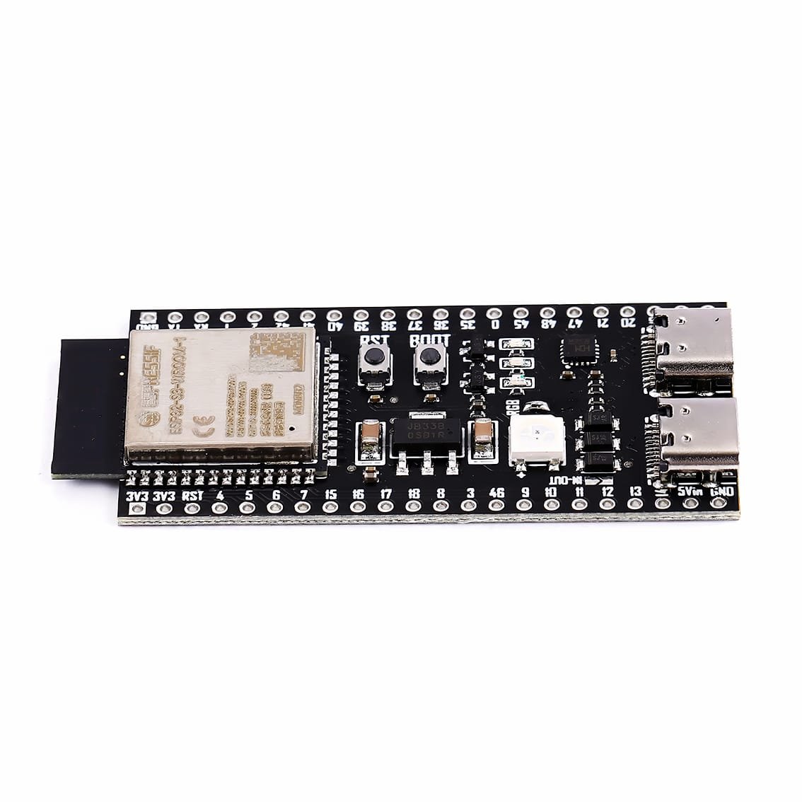
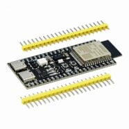
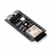
You may have purchased the latest ESP32 dev board variant, such as the ESP32-S3 Devkit-C1, to experiment with your projects. However, you realize it’s not straightforward to make an LED Blinky code to test it out. The reason is that Espressif decided to place a Neopixel-type RGB LED (WS2812B) onboard the DevKitC-1. So how do you make your ESP32-S3 blink its RGB LED?
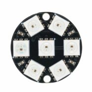
The WS2812B RGB LED
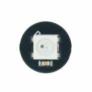
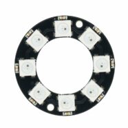
The WS2812B RGB is not your typical 3-color SMD 5050 LED. It’s a serially addressable type. It uses a one-wire serial interface to connect to an MCU to set its color and brightness through a 24-bit pulse train with strict timing specifications. Additionally, this LED has both serial-in and out pins, which makes it easy to daisy-chain several WS2812Bs together. With this, WS2812B LEDs have 2 power pins, a digital input pin (DI), and a digital output pin (DO).
How the ESP32-S3 controls the WS2812B LED
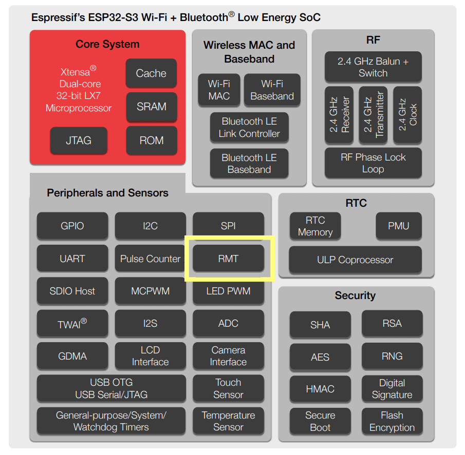
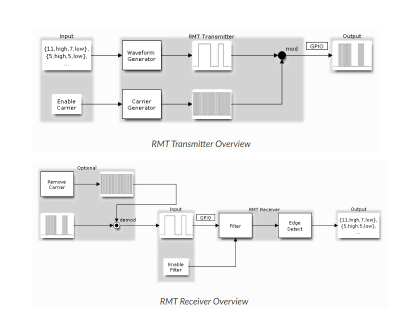
The ESP32-S3 controls the WS2812B through its Remote Control Transceiver (RMT) peripheral. RMT was initially developed to transmit or receive complex IR (infrared) signals for remote control operations. However, due to RMTs flexibility, it can also be used as a general-purpose sequence generator or to transmit signals in a hardware-controlled loop. These functions are especially suited to driving WS2812B LEDs. In line with this, as you’ll see later, driving WS2812B LEDs need additional libraries instead of just toggling GPIO’s as what’s used for regular LEDs.
Blinky Code for the ESP32-S3 DevKitC-1
Fortunately, all the intricacies of the RMT peripheral have been abstracted away from the user through the Espressif Arduino library. Below are the steps to get a simple Blinky code working for your ESP32-S3 DevKit.
Arduino IDE
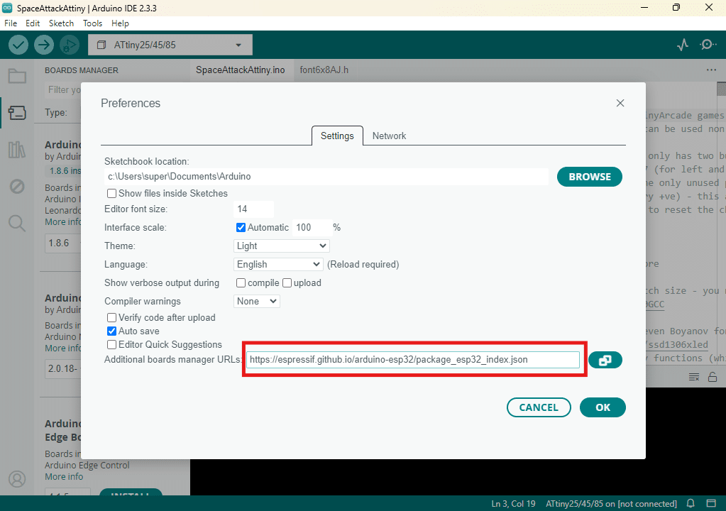
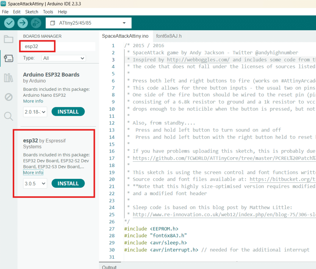
Open your Arduino IDE , go to File -> Preferences and on Additional Boards Manager, enter the following text:
2. Go to Tools -> Board -> Board Manager. Find ESP32 by Espressif and install it. You should see on the output that it was installed successfully.
You are now ready to connect an Espressif board to Arduino IDE.
3. Open a new Sketch and then connect your ESP32-S3 Devkit to an available USB slot on your PC through a USB cable. If you have the correct device drivers on your PC for your ESP32 boards, you should not encounter any issues.
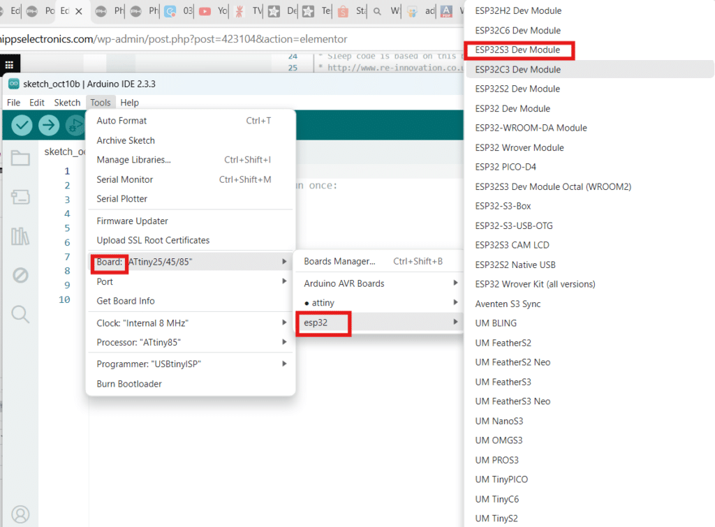
4. Go to Tools -> Board: -> esp32 then pick the specific ESP32 module you have on the list. Here, ESP32S3 Dev Module is chosen.
5. Connect to Serial by clicking Select other board and port above. Select the proper serial port your ESP32 board has connected to. If all goes well then you should see your ESP32S3 Dev Module connected successfully above.
6. Open the ESP32 Example Blinky project by going to File -> Examples -> ESP32 -> RMT -> RMTWrite_RGB_LED
7. Important. In the code, you must define the correct port on your ESP32 that connects to the WS2812B RGB module. Here, for example, port 48 is used for a clone ESP32-S3 DevKitC-1. Yours maybe different, so please check it. You don’t have to modify the number of LEDs to drive (NR_OF_LEDS) since the serial data latching feature of the WS2812B can catch up with the code to blink this single LED.
8. Go ahead and upload the code to your device. You should see a simple blinking of the RGB LED (white color – R, G, and B) on your ESP32 now.
Hope this ESP32-S3 blink RGB LED tutorial has helped 🙂