Use your I2S microphone to record voice and output that voice to your I2S DAC Audio amplifier, creating an ESP32-S3 voice recorder.
INTRODUCTION
On I2S Audio on the ESP32-S3, you were able to utilize your I2S skills by plotting a graph of your I2S microphone audio data and outputting digital sound (using a triangular waveform) on your I2S DAC amplifier. This time, you’ll be able to integrate those skills by creating a stand-alone ESP32 voice recorder. The process is simple: capture voice data via the I2S mic and save it in PSRAM; after that, output that audio data to your I2S DAC using a speaker.
What Specific kind of ESP32 to use
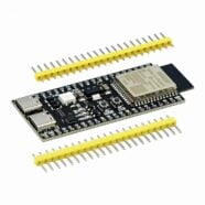
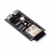
Last time, an ESP32-S3 DevKit-C1 was used for the examples. This dev board is especially suited for the voice recorder application since it has several variants. Note that it’s best to use a version that has an 8MB PSRAM installed. Specifically, the one used here is an ESP32-S3 DevKit-C1 with an ESP32-S3-WROOM-1 with 16MB Flash and 8MB PSRAM. The 8MB PSRAM is more than enough to hold several seconds of temporary voice audio data.
Circuit Setup
The circuit setup of the last exercise can be used on the ESP32 voice recorder.
| INMP441 Pin | ESP32-S3 Pin | Function |
|---|---|---|
| VCC | 3.3V | Power supply (3.3V only) |
| GND | GND | Ground |
| SCK (BCLK) | GPIO 47 | I2S Bit Clock (BCLK) |
| WS (LRCLK) | GPIO 10 | I2S Word Select (LRCLK) |
| SD (DOUT) | GPIO 21 | I2S Serial Data Input (from mic) |
| L/R | GND | Left Channel Mic Select |
Note that the L/R port is connected to GND so that a Left Channel Mic configuration is selected.
| MAX98357A Pin | ESP32-S3 Pin | Function |
|---|---|---|
| VIN | 3.3V or 5V | Power supply (supports both) |
| GND | GND | Ground |
| BCLK | GPIO 2 | I2S Bit Clock |
| LRCLK | GPIO 1 | I2S Word Select (Left/Right Clock) |
| DIN | GPIO 38 | I2S Data Output from ESP32 |
| GAIN | GND | Sets output gain 12 dB |
| SD | GPIO 4 | Optional shutdown control |
| ESP32-S3-DevKit-C1 | Tact Switch |
|---|---|
| GPIO12 | Start Recording |
Here, the Gain pin is set to GND, indicating a gain of 12dB. The SD (Shutdown) pin can be assigned to any free GPIO port, so you can disable the speaker output.


A push button is used to start the audio recording session.
Creating your ESP32 Voice Recording Code
I2S Audio on the ESP32-S3 taught you to create a configuration and pin setup for the I2S ports of your ESP32. You were also able to both transmit and receive I2S audio data through the i2s_write() and i2s_read() functions, respectively. These functions have a powerful DMA (Direct Memory Access) feature that can stream and buffer I2S data on their own, without wasting precious CPU clock cycles. This time around, you’ll need another powerful peripheral, which is the PSRAM.
How to use the PSRAM
The PSRAM is an optional extension memory component of the ESP32-S3. This RAM is best utilized using a very fast SPI connection. Specifically, using either quad or octal SPI. Additionally, optional external flash storage can also be accessed through Octal or Quad SPI. There are different ESP32-S3 modules that you can choose from to select which configuration you want.
Below is the Flash/PSRAM block diagram for an ESP32-S3-WROOM-1
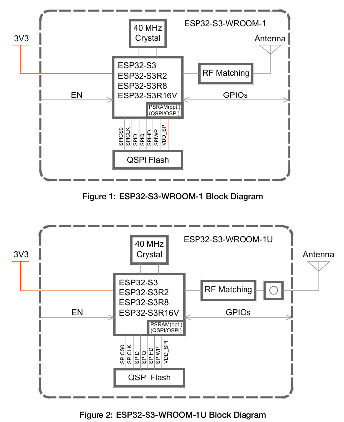
By default, your ESP32-S3 can access 512KB of internal PSRAM and 384 KB of ROM. In order to access extended PSRAM, you’ll need to activate this in your configuration and also write special attributes in your code. Below is a configuration setting in the Arduino IDE you can use to activate PSRAM. Additionally, don’t forget to select your ESP32S3 Dev Module by going to Tools -> Board -> esp32.


You may also use the other settings to make your ESP32 voice recorder similar to the example here.
To use PSRAM in code, initially set an integer pointer variable to NULL
int16_t *AudioBuffer = NULL;
Next, during runtime, dynamically allocate that variable in the heap through heaps_caps_malloc together with an attribute of MALLOC_CAP_SPIRAM
AudioBuffer = (int16_t *)heap_caps_malloc(BUFFER_SIZE, MALLOC_CAP_SPIRAM);
Where BUFFER_SIZE is the actual size of AudioBuffer in bytes.
You can now freely use the PSRAM space to read I2S data like in:
i2s_read(I2S_NUM_0, AudioBuffer, BUFFER_SIZE, &bytes_in, portMAX_DELAY);
where the output will be stored in the AudioBuffer variable located in PSRAM. Similarly, you can write to your I2S peripheral with:
i2s_write(I2S_NUM_1, AudioBuffer, bytes_in, &bytes_out, portMAX_DELAY);
Actual Code
To have some visuals, the Neopixel of the ESP32-S3 will be used, which is connected to GPIO48. This LED will light Red when recording, then Green when outputting audio. So you’ll need the NeoPixel library and some definitions:
					#include <Adafruit_NeoPixel.h>
#define LED_PIN     48       // GPIO pin connected to WS2821 data line
#define NUM_LEDS    1        // Number of LEDs in the strip (usually 1 for built-in)
#define LED_TYPE    NEO_GRB  // uses GRB order
Adafruit_NeoPixel strip(NUM_LEDS, LED_PIN, LED_TYPE + NEO_KHZ800);
Below is the full code for voice recording on your ESP32-S3:
					#include <Adafruit_NeoPixel.h>
#include <driver/i2s.h>

#define LED_PIN     48       // GPIO pin connected to WS2821 data line
#define NUM_LEDS    1        // Number of LEDs in the strip (usually 1 for built-in)
#define LED_TYPE    NEO_GRB  // uses GRB order

#include "driver/i2s.h"

#define BUTTON 12

#define I2S_MIC_BCLK 47
#define I2S_MIC_LRC 10
#define I2S_MIC_DIN 21
#define I2S_MIC_PORT I2S_NUM_1

#define I2S_SPK_BCLK 2
#define I2S_SPK_LRC 1
#define I2S_SPK_DOUT 38
#define I2S_SPK_SD 4
#define I2S_SPK_PORT I2S_NUM_0

#define SAMPLE_RATE 44100
#define BITS_PER_SAMPLE I2S_BITS_PER_SAMPLE_16BIT
#define BYTES_PER_SAMPLE BITS_PER_SAMPLE / 8
#define REC_DURATION 5
#define BUFFER_SIZE (REC_DURATION * SAMPLE_RATE * BYTES_PER_SAMPLE)

Adafruit_NeoPixel strip(NUM_LEDS, LED_PIN, LED_TYPE + NEO_KHZ800);

int16_t *AudioBuffer = NULL;
size_t bytes_in;
size_t bytes_out;

void setup() {

  strip.begin();
  strip.show(); // Initialize all pixels to 'off'

  Serial.begin(115200);
  delay(500);
  pinMode(BUTTON, INPUT_PULLUP);

  pinMode(I2S_SPK_SD, OUTPUT);  // turn OFF DAC first
  digitalWrite(I2S_SPK_SD, LOW);

  i2s_config_t i2s_mic_config = {
    .mode = (i2s_mode_t)(I2S_MODE_MASTER | I2S_MODE_RX),
    .sample_rate = SAMPLE_RATE,
    .bits_per_sample = BITS_PER_SAMPLE,
    .channel_format = I2S_CHANNEL_FMT_ONLY_LEFT,
    .communication_format = I2S_COMM_FORMAT_STAND_I2S,
    .intr_alloc_flags = 0,
    .dma_buf_count = 8,
    .dma_buf_len = 1024
  };
  i2s_pin_config_t i2s_mic_pin_config = {
    .bck_io_num = I2S_MIC_BCLK, .ws_io_num = I2S_MIC_LRC, .data_out_num = I2S_PIN_NO_CHANGE, .data_in_num = I2S_MIC_DIN
  };
  i2s_driver_install(I2S_MIC_PORT, &i2s_mic_config, 0, NULL);
  i2s_set_pin(I2S_MIC_PORT, &i2s_mic_pin_config);

  i2s_config_t i2s_spk_config = {
    .mode = (i2s_mode_t)(I2S_MODE_MASTER | I2S_MODE_TX),
    .sample_rate = SAMPLE_RATE,
    .bits_per_sample = BITS_PER_SAMPLE,
    .channel_format = I2S_CHANNEL_FMT_ONLY_LEFT,
    .communication_format = I2S_COMM_FORMAT_STAND_I2S,
    .intr_alloc_flags = 0,
    .dma_buf_count = 8,
    .dma_buf_len = 1024
  };
  i2s_pin_config_t i2s_spk_pin_config = {
    .bck_io_num = I2S_SPK_BCLK, .ws_io_num = I2S_SPK_LRC, .data_out_num = I2S_SPK_DOUT, .data_in_num = I2S_PIN_NO_CHANGE
  };

  i2s_driver_install(I2S_SPK_PORT, &i2s_spk_config, 0, NULL);
  i2s_set_pin(I2S_SPK_PORT, &i2s_spk_pin_config);

  // Set up audio buffer in PSRAM
  AudioBuffer = (int16_t *)heap_caps_malloc(BUFFER_SIZE, MALLOC_CAP_SPIRAM);
  if (AudioBuffer == NULL) {
    Serial.println("PSRAM could not be allocated");
    while(1);
  }else{
    Serial.println("Buffer created in PSRAM.");
  }

}

void loop() {

  if(digitalRead(BUTTON) == 0){
    delay(300); // debounce

    Serial.println("Begin Voice Recording...");

    strip.setPixelColor(0, strip.Color(255, 0, 0)); // Red
    strip.show();

    // read I2S MIC

    i2s_read(I2S_MIC_PORT, AudioBuffer, BUFFER_SIZE, &bytes_in, portMAX_DELAY);
    Serial.print(bytes_in); Serial.println(" Recorded");

    strip.setPixelColor(0, strip.Color(0, 255, 0)); // Green
    strip.show();

    // Activate DAC
    digitalWrite(I2S_SPK_SD, HIGH);

    // Output Audio Data
    Serial.println("Playing Audio Data");
    i2s_write(I2S_SPK_PORT, AudioBuffer, bytes_in, &bytes_out, portMAX_DELAY);
    Serial.print(bytes_out); Serial.println(" Played");

    // Turn off DAC amp
    digitalWrite(I2S_SPK_SD, LOW);

    strip.setPixelColor(0, strip.Color(0, 0, 0)); // OFF
    strip.show();

  }

}
As in the previous exercise, port definitions are declared for the MIC and SPKR terminals. The shutdown pin of the MAX98357A is also used here. The audio buffer size is proportional to the length of the recording and the sampling rate of the audio data.
					#include "driver/i2s.h"

#define BUTTON 12

#define I2S_MIC_BCLK 47
#define I2S_MIC_LRC 10
#define I2S_MIC_DIN 21
#define I2S_MIC_PORT I2S_NUM_1

#define I2S_SPK_BCLK 2
#define I2S_SPK_LRC 1
#define I2S_SPK_DOUT 38
#define I2S_SPK_SD 4
#define I2S_SPK_PORT I2S_NUM_0

#define SAMPLE_RATE 44100
#define BITS_PER_SAMPLE I2S_BITS_PER_SAMPLE_16BIT
#define BYTES_PER_SAMPLE BITS_PER_SAMPLE / 8
#define REC_DURATION 5
#define BUFFER_SIZE (REC_DURATION * SAMPLE_RATE * BYTES_PER_SAMPLE)
On setup, the Neopixel LED and AudioBuffer integer are initialized. The I2S configuration for the MIC and SPKR is also done here. The AudioBuffer variable is specifically placed in PSRAM.
					Adafruit_NeoPixel strip(NUM_LEDS, LED_PIN, LED_TYPE + NEO_KHZ800);

int16_t *AudioBuffer = NULL;
size_t bytes_in;
size_t bytes_out;

void setup() {

  strip.begin();
  strip.show(); // Initialize all pixels to 'off'

  Serial.begin(115200);
  delay(500);
  pinMode(BUTTON, INPUT_PULLUP);

  pinMode(I2S_SPK_SD, OUTPUT);  // turn OFF DAC first
  digitalWrite(I2S_SPK_SD, LOW);

  i2s_config_t i2s_mic_config = {
    .mode = (i2s_mode_t)(I2S_MODE_MASTER | I2S_MODE_RX),
    .sample_rate = SAMPLE_RATE,
    .bits_per_sample = BITS_PER_SAMPLE,
    .channel_format = I2S_CHANNEL_FMT_ONLY_LEFT,
    .communication_format = I2S_COMM_FORMAT_STAND_I2S,
    .intr_alloc_flags = 0,
    .dma_buf_count = 8,
    .dma_buf_len = 1024
  };
  i2s_pin_config_t i2s_mic_pin_config = {
    .bck_io_num = I2S_MIC_BCLK, .ws_io_num = I2S_MIC_LRC, .data_out_num = I2S_PIN_NO_CHANGE, .data_in_num = I2S_MIC_DIN
  };
  i2s_driver_install(I2S_MIC_PORT, &i2s_mic_config, 0, NULL);
  i2s_set_pin(I2S_MIC_PORT, &i2s_mic_pin_config);

  i2s_config_t i2s_spk_config = {
    .mode = (i2s_mode_t)(I2S_MODE_MASTER | I2S_MODE_TX),
    .sample_rate = SAMPLE_RATE,
    .bits_per_sample = BITS_PER_SAMPLE,
    .channel_format = I2S_CHANNEL_FMT_ONLY_LEFT,
    .communication_format = I2S_COMM_FORMAT_STAND_I2S,
    .intr_alloc_flags = 0,
    .dma_buf_count = 8,
    .dma_buf_len = 1024
  };
  i2s_pin_config_t i2s_spk_pin_config = {
    .bck_io_num = I2S_SPK_BCLK, .ws_io_num = I2S_SPK_LRC, .data_out_num = I2S_SPK_DOUT, .data_in_num = I2S_PIN_NO_CHANGE
  };

  i2s_driver_install(I2S_SPK_PORT, &i2s_spk_config, 0, NULL);
  i2s_set_pin(I2S_SPK_PORT, &i2s_spk_pin_config);

  // Set up audio buffer in PSRAM
  AudioBuffer = (int16_t *)heap_caps_malloc(BUFFER_SIZE, MALLOC_CAP_SPIRAM);
  if (AudioBuffer == NULL) {
    Serial.println("PSRAM could not be allocated");
    while(1);
  }else{
    Serial.println("Buffer created in PSRAM.");
  }

}
The main loop reads a button press to start recording. The i2sread( ) command gets the 16-bit audio data coming from the mic. The i2write( ) command outputs the 16-bit audio data to the DAC amp. These commands both use the same AudioBuffer variable located in PSRAM. The Neopixel LED is lit accordingly, and the SD (Shutdown pin) of the DAC is also used. You can adjust the sampling rate and record duration according to your liking.
					void loop() {

  if(digitalRead(BUTTON) == 0){
    delay(300); // debounce

    Serial.println("Begin Voice Recording...");

    strip.setPixelColor(0, strip.Color(255, 0, 0)); // Red
    strip.show();

    // read I2S MIC

    i2s_read(I2S_MIC_PORT, AudioBuffer, BUFFER_SIZE, &bytes_in, portMAX_DELAY);
    Serial.print(bytes_in); Serial.println(" Recorded");

    strip.setPixelColor(0, strip.Color(0, 255, 0)); // Green
    strip.show();


    // Activate DAC
    digitalWrite(I2S_SPK_SD, HIGH);

    // Output Audio Data
    Serial.println("Playing Audio Data");
    i2s_write(I2S_SPK_PORT, AudioBuffer, bytes_in, &bytes_out, portMAX_DELAY);
    Serial.print(bytes_out); Serial.println(" Played");

    // Turn off DAC amp
    digitalWrite(I2S_SPK_SD, LOW);

    strip.setPixelColor(0, strip.Color(0, 0, 0)); // OFF
    strip.show();

  }

}
Below is a video demo of the setup running:
Improvements in the circuit and code
If you were to look at the I2S peripheral of the ESP32-S3, you’ll see that it can run in half-duplex mode. This means that each I2S can transmit and receive data (not simultaneously). The Mic and Speaker don’t transmit and receive data at the same time. With this, you can theoretically use a single I2S port for both the MIC and Speaker. This means fewer wires because you just need a single BCLK, WS, and SD pin connection to both the Mic and Speaker.