If you’re struggling to set up your automated water tank system using a float switch level sensor, this is a good place to start.
Introduction
Creating an automated water tank system alleviates the user from always trying to monitor the water level of their tank. With this, you don’t have to keep watch when filling up your water tank, as well as when it becomes empty. In the long run, you can save precious resources such as time, additional employees, and prevent unnecessary water spillage or empty tanks.
HOw a Float Switch Level Sensor Works
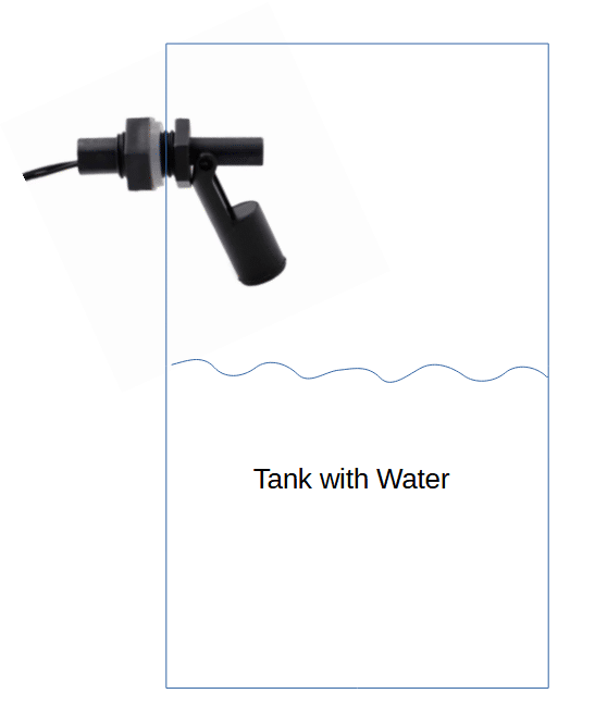
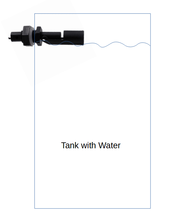
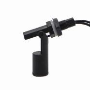
A float switch level sensor is composed of a mechanical hinge attached to a buoyant material. This material, when submerged in water, will float, causing the hinge to move. The hinge is electrically connected to contacts that open or close a switch depending on its configuration. Similarly, when the buoyant material is already floating and submerged in water, the hinge will move in the opposite direction if water is removed. This will cause the switch to open or close in the opposite state compared to when the hinge was not previously submerged.
Limitations of a Float Switch Sensor
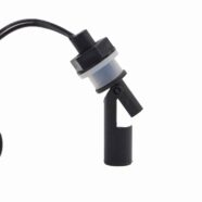
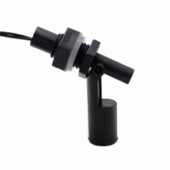
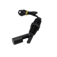
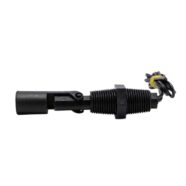
You may think you can use the electrical contacts of a float switch sensor to control some equipment. However, some float switches’ contacts don’t have the capacity to drive powerful loads such as a water pump. Below is an example of a float switch level sensor specification:
Specifications:
Material: Plastic
Color: Black
Mounting: Side Mounted
Orientation: Can be set as Normally Open / Normally Closed
Cable Length: ~400mm
Float Length: 85mm
Max Switching Voltage: 100Vdc
Max Contact Rating: 10W
Max Breakdown Voltage: 220Vdc
Max Switching Current: 0.5A
Max Carry Resistance: 1.0A
Max Contact Resistance: 100mΩ
Operating Temperature: -10°c – 85°c
Thread Size: M16X2 Thread
Note that based on the Max Switching current and Max Carry Resistance values, the contact cannot carry more than an amp (even less for switching current). With this, you’ll definitely need a buffer relay to control your water pump.
Adding a relay to control your Water Pump
You can use a relay module with a trigger input and a normally open or closed (NO and NC) output to buffer the float switch level sensor signal, as seen in the wiring diagram below:
Here, notice that the relay IN trigger line is connected to one of the terminals of the float level switch. The other terminal of the float is connected to the positive power source or battery terminal. With this setup, when the float switch is activated, a positive voltage triggers the relay module, thereby activating or deactivating your water pump according to your relay configuratipon.
Notice that, based on the relay’s output side switch, this portion does not generate any voltage and is not self-powered. Instead, you’ll have to supply power to this output switch (NC or NO and C) in series with your load or water pump.