If you’re into miniaturization and mobility of your board interconnections, flex PCB designs are the way to go. Read through this article to learn more about them.
InTroduction
There are several ways to interconnect printed circuit boards or components together on your projects. If you’re the usual electronic hobbyist and want a simple straightforward solution, you can find a male/female header connector pair with wires and use them easily on your boards. This is okay for simple projects. However, when you’re left with a small headroom of space inside your chassis, you should think otherwise of using a different method of connecting your boards and components.
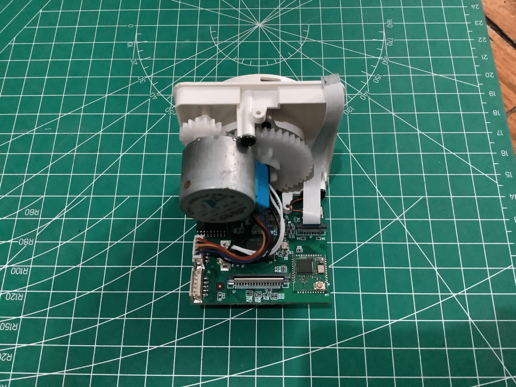
An example of a header connector with wires connecting motors to your board.
Another issue is boards or components that move or are not fixed. It may be hard for standard connectors to survive the wear and tear of such a setup. You may wonder how previous technologies such as CD-ROMS and disk drives connect their moving parts to their drivers or controllers.
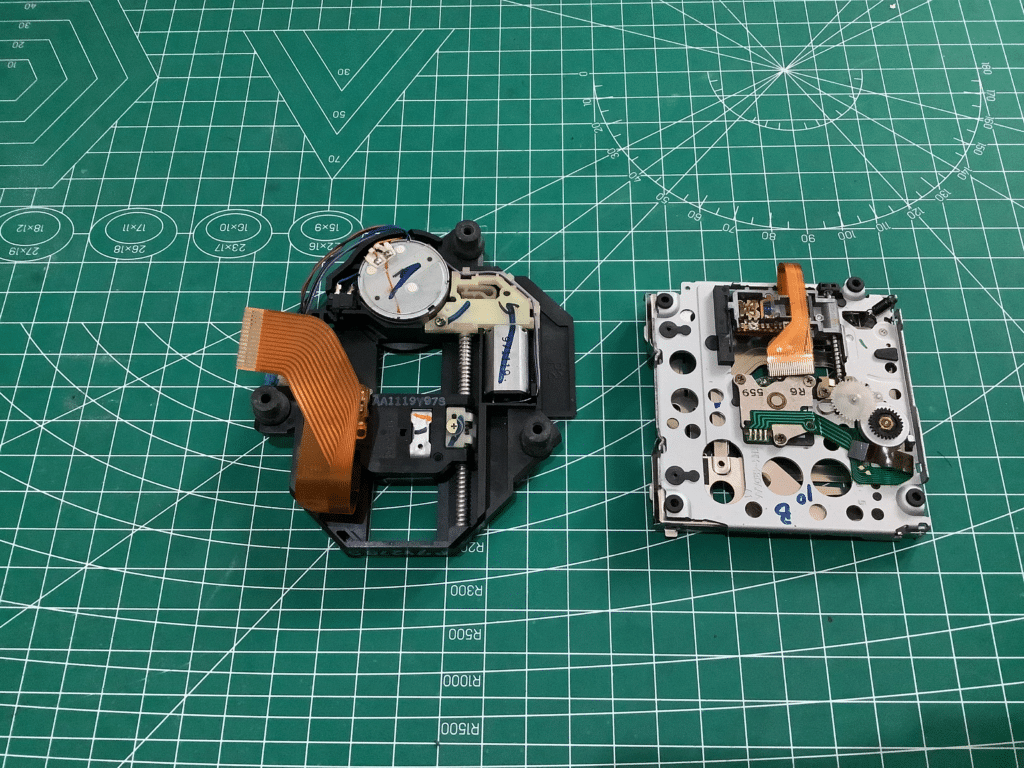
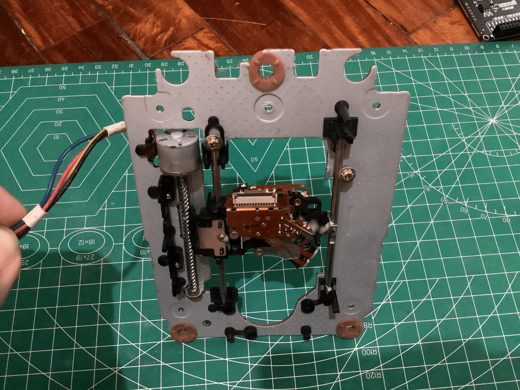
Examples of flex PCBs used on disk drives
Flex PCB incorporated on a Blu-ray drive to save space.
This is where Flex PCB designs may come into play.
What are Flex PCBs
Flex PCBs, as their name implies, are circuit layouts that can flex or bend to accommodate small spaces or mobility constraints. Their construction is different from standard rigid PCBs. The base material used in flex PCBs is a plastic material called Polyimide. This material allows the bending of the flex boards. Additionally, the copper foil tracks on a flex PCB are made of rolled-annealed copper foil to accommodate the bending.
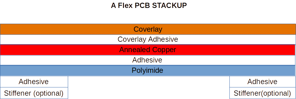
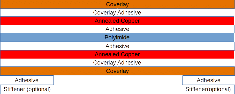
Above, you’ll see the common stackup structure of a single-layer flex PCB. The Coverlay is a plastic material that acts as a solder mask to protect the rolled-annealed copper tracks. The Polyimide layer is the base material responsible for the flexible property of the board. Adding stiffeners at the end of the flex PCB allows the board to be inserted easily inside an FPC connector.
If you want a multiple-layer flex PCB stack up, you just have to repeat the copper, and adhesive layers along with the Polyimide base and coverlay layers as seen above.
HOw do you Create a Flex PCB?
Interestingly, you can create a flex PCB just like any ordinary rigid (FR4-based) PCB. The reason is flex PCBs use the same basic detail layers as a rigid PCB. Such layers as solder mask, paste, silkscreen, copper foil, fabrication layers, and others. However, note that there are design rules that you must follow when using plastic materials and wiring tracks on them.
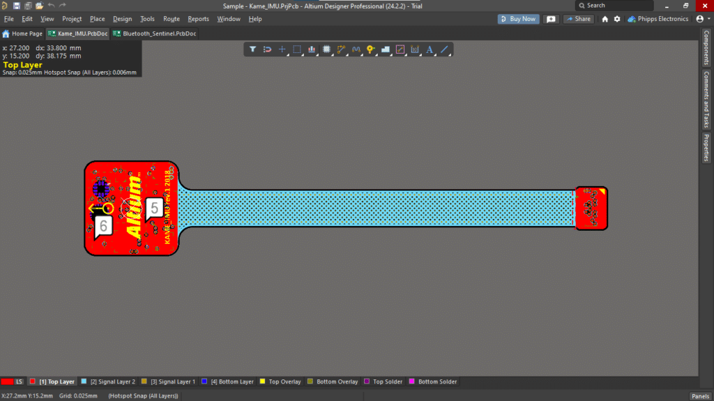
An example Flex PCB project from Altium Designer utilizing the common user detail layers below.
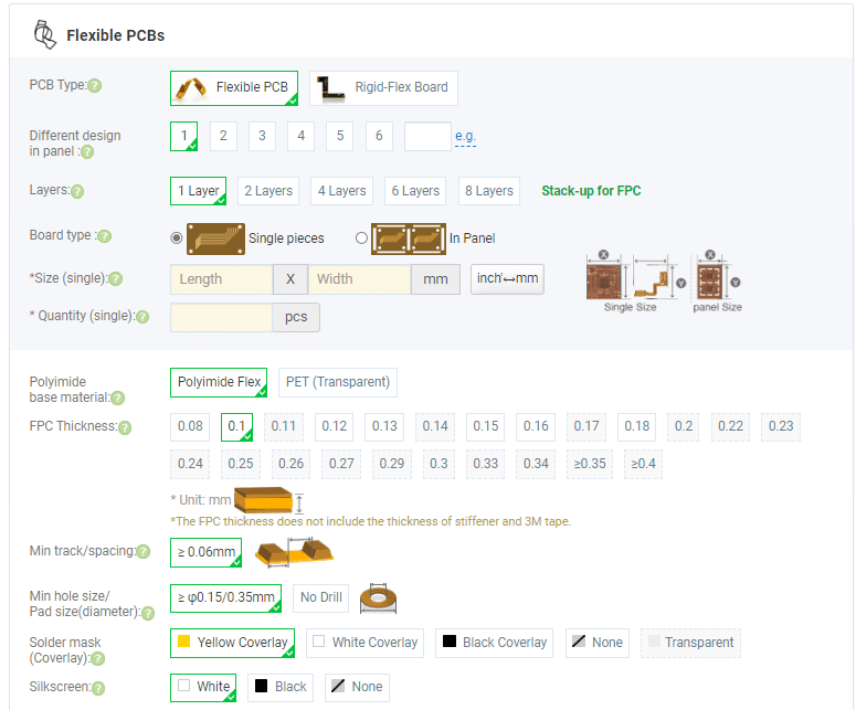
The difference lies in the manufacturing process. Flex PCB’s stack up, materials, and processes should be explicitly said to your PCB manufacturer. Before, manufacturing flex PCBs was complicated and only available to companies that could afford them. Fortunately, even casual electronics hobbyists can now create and order a flex PCB online. Flex PCB manufacturing costs have drastically decreased through the years and the ordering process has become automated. Below is a cart-based checkout system for creating and ordering flex PCBs from PCB Way.
HOw About Rigid-Flex PCBs?
Rigid-flex PCBs are a combination of Rigid (common FR4 PCBs) and Flex PCBs all in one panel assembly. This will be discussed in the next blog.
SUBSCRIBE FOR NEW POST ALERTS
Subscribe to be the first to know when we publish a new article!