Interested in making your 3D model electronic enclosure in FreeCAD for your projects? Want to learn how to do it through a step-by-step guide? Read through this article to find out.
Introduction
Last time, you learned how to Generate 3D Models in KiCAD. Usually, you’ll need an enclosure for this. Your project may feel fragile, unprotected, and incomplete without this enclosure. There are available enclosures that you can buy, however, not all will fit. With this, you should be ready to create your own 3D electronic enclosure.
What is FreeCAD?
FreeCAD is a free and open-source CAD/CAM software. It is called a 3D parametric modeler since you can change parameters as you make your design. This means you can select, change or undo certain characteristics of your project (some constrained by a hierarchal precedence) without destroying your project’s overall structure.
With FreeCAD, you can create any custom 3D models to represent your project. These projects can vary. Examples of such projects are enclosures, gears, car, household, and machine parts and the like.
Additionally, FreeCAD has CAM and CNC workbenches. This means you don’t need separate software to translate your 3D Model into G-code or instructions for cutting tools.
How to Make a FreeCAD Model for your Electronic Enclosure
Here are the steps to create your electronic enclosure in FreeCAD.
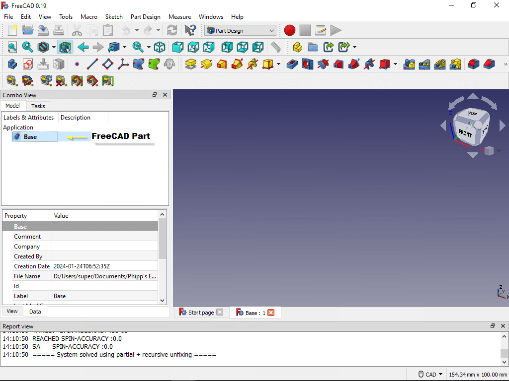
1. Create a New FreeCAD Document
First start a new FreeCAD document by selecting File -> New. You may see an Unnamed document at first. You can rename this by going to File-> Save As then rename your document. Here, the electronic enclosure document will be named Base. You’ll also see a Model (your models) and a Task (possible tasks) tab that you can switch to while working on this design.
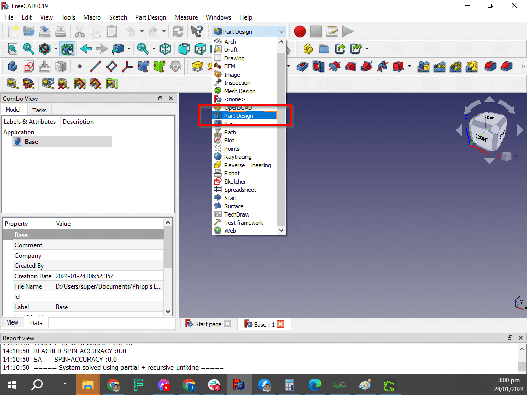
2. Begin Creating a Part. Pick the Part Design Workbench
In order to begin designing a part, choose the Part Design workbench. FreeCAD, like other 3D modelling software incorporate workbenches to streamline the design process. Other workbenches include CNC, Assembly, Draft, etc.
3. Create a New Body
A FreeCAD project should have one or more bodies. These bodies combine to produce your actual 3D model. With this, with your Base part highlighted, click the Create a New Body icon.
Rename this Body to your liking. Press F2 to rename it. Here the default name Body is used.
Display the Origin of your body by clicking on Origin and then pressing spacebar. The spacebar serves as a display switch for different bodies and its element. Here you’ll see the 3D planes you’ll work on with our body.
4. Create a Base Sketch to Extrude Your Body Later
While your Base Body is active, create a Sketch on it. A Sketch is a 2D representation of your body. Later, you’ll extrude this sketch to become 3D. Click the create a new sketch icon and then choose a plane where the sketch will be laid out. Here, the X-Y plane (from the body’s Origin) is used.
5. Work on Your Sketch
Work on your Sketch by using the Sketch tools above. Create a Rectangle first. In Sketches, remember that you have to create constraints. Constraints creates precise 2D sketches that are fully defined. This will help you prevent issues during 3D extrusion.
Below is an example of a fully constrained rectangular area (100mm x 75mm) for your Base body. It consists of using the Symmetry tool and the Horizontal and Vertical Fix Distance tools. Once you fully constrain your Sketch, click close to go back to the Model tab. You’ll now see your Sketch in 3D space ready to be extruded.
6. Pad or Extrude your Sketch
You may now extrude or pad this sketch to convert it into a 3D Model. Let the extrusion length be 30mm. Notice that the body is a solid rectangular mass.
To make it look like the base of an enclosure you have to define a thickness to that body. Pick the top face of the body to define your working area. Next, click the Make a Thick Solid tool. Enter at least 3mm for the thickness. Choose Intersection as join type and make the thickness inward (making the thickness inwards makes it easier to recall dimensions when you’re about to make your cover).
That’s it! You’ve created your base body model for your electronic enclosure in FreeCAD. In the next part, you’ll learn to add corner pillars with screw holes to be able to mount a cover body. You’ll also be able to add spacers with mounting holes on your base to mount your PCB.