Learn to place each of your components in the built-in assembly workbench accurately in this article.
INtroduction
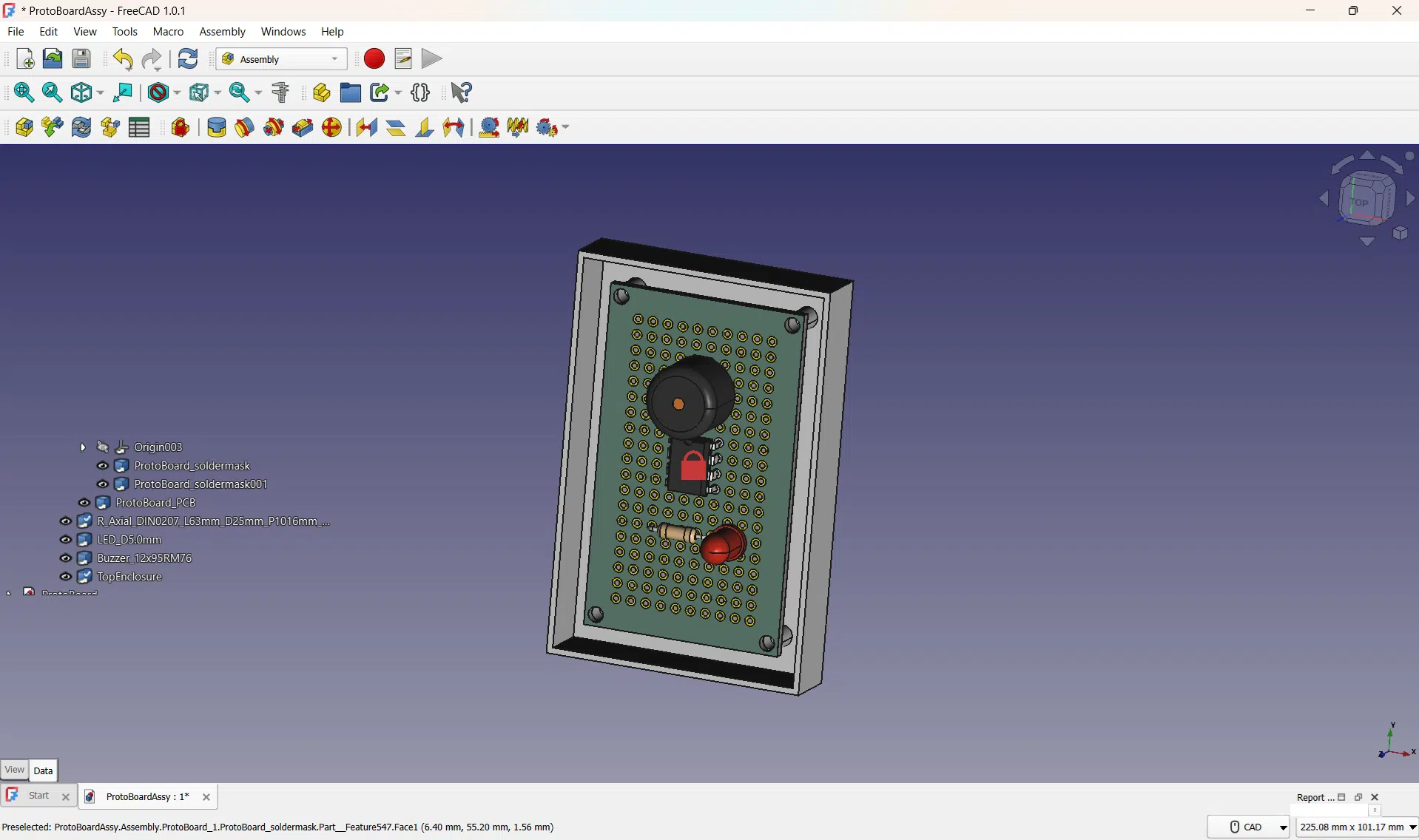
Last time, you were able to create an assembly drawing and insert components unto it by using the built-in assembly workbench in FreeCAD 1.0x. This time, you’ll learn how to accurately place those components easily without the hassles of learning or using an LCS (Local Coordinate System), as what’s being done in assembly4, Part Design, or Part workbenches.
Why the Built-in Assembly Workbench is Easy to Work with?
As described earlier, the built-in assembly workbench of FreeCAD 1.0x handles the LCS internally so the user does not have to deal with the complexity of this coordinate system. Here, you can attach your assembly components by simply using joints. Additionally, you can conveniently move your components by dragging them with your mouse or using an arrow similar do doing a transform.
PLacing the Components of the electronic Assembly
Decide which component to fix or anchor
For demonstration purposes, you can change which component you want fixed or grounded. Continuing from the previous FreeCAD project, highlight that component and then click the Toggle Grounded Joint tool. You should see that component grounded on the Joints section of the assembly. Next, delete the previous grounded joint if you want to. You need at least one grounded component to continue making joints.
As this is just a demo to illustrate grounded joints, the fixed component will still be the PCB in the next examples.
Attach a component's pin by using the Create Cylindrical Joint tool
The Cylindrical Joint Tool allows you to place a component’s pin through a through-hole pad so that you can stuff that component on your board. With this, you have to select both the component’s leg and the through-hole pad. Note that defining a cylindrical joint alone may not fully fix that part, and you need to define other parameters as you’ll see later.
Fix the height of the component from the board
You can fix the height of that component by using the Create Distance Joint Tool. Select an area from the component and the board surface for this. Here, the flat part of the leg of the component was selected (as this surface is parallel to the surface of the board). Define a measurement that’s right for you.
You’ll see, though, that you can still move the resistor and sway it because of the free angle of that cylindrical joint.
Fix the angle of that cylindrical joint
With this, you have to fix the min and max angles of that joint accordingly. You don’t want that joint moving (as it’s really soldered). You could have also done this earlier upon defining the joint.
Interestingly, you could still use the Cylindrical Joint tool even if the pin to join is non-cylindrical (such as IC and square beam type pins). The example below inserts the square beam leg of an LED.
Do the same with the Buzzer component. Notice here, the bottom of the buzzer’s body was used for the distance joint (with 0mm spacing) along with the PCB top surface.
Fix the PCB on the enclosure
Lastly, you can place and fix the PCB on the chassis by creating a Fixed Joint. Choose the PCB and the enclosure mounting holes as joints for this. A fixed joint is a non-movable joint.
That’s it. You’ve just learned how to use FreeCAD 1.0 assembly workbench (the built-in assembly workbench). You’re now ready to create really simple and easy-to-use joints-based assemblies.