There will be times when we are building projects like Remote Controlled Cars or Line follower robots. This IC is compulsory of such projects!
Why do we use the L293D?
When working on an RC car or line follower robot project, A few problems arise. For example – We can’t power the motors through Arduino because motors usually need a lot of current to run and using Arduino for such heavy loads is just not really a good idea. Secondly, the motors need to be able to turn in both directions. Even though changing polarity does solve this issue, but doing that by hand is not realistic. All of these problems are solved using just 1 solution: L293D
What is the L293D?
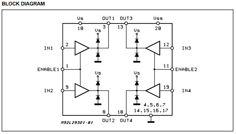
The device is a monolithic integrated high voltage, high current four channel driver designed to accept standard DTL or TTL logic levels and drive inductive loads (such as relays solenoids, DC and stepping motors) and switching power transistors. To simplify use as two bridges each pair of channels is equipped with an enable input. A separate supply input is provided for the logic, allowing operation at a lower voltage and internal clamp diodes are included. This device is suitable for use in switching applications at frequencies up to 5 kHz.
The internal construction of the IC looks like this.
For more details, Check the Datasheet here.
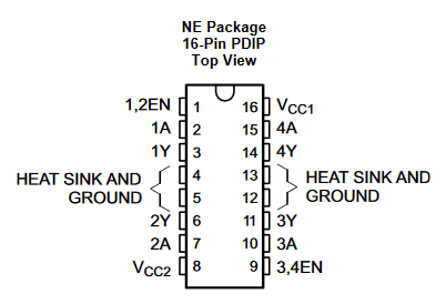
| PIN | Type | Description | |
|---|---|---|---|
| NAME | NO. | ||
| 1, 2EN | 1 | I | Enable driver channels 1 and 2 (active high input) |
| <1:4>A | 2, 7, 10, 15 | I | Driver inputs, noninverting |
| <1:4>Y | 3, 6, 11, 14 | O | Driver outputs |
| 3, 4EN | 9 | I | Enable driver channels 3 and 4 (active high input) |
| GROUND | 4, 5, 12, 13 | - | Device ground and heat sink pin. Connect to printed-circuit-board ground plane with multiple vias |
| VCC1 | 16 | - | 5V supply for internal logic translation |
| VCC2 | 8 | - | Power VCC for drivers 4.5V to 36V |
Wiring Diagram
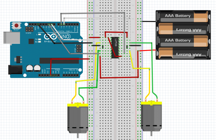
We have connected the VCC1 with Arduino’s 5V as that supplies power for the IC’s internal logic translation. But we connected VCC2 to an external power source because the power needed to drive the motors is consumed from VCC2.
1 and 9 are the enable pins, we always keep that high because we always want to be able to drive the motors.
The ground pins are all connected to the ground.
The input pins are connected to Arduino’s digital pins.
The Code
					int p1 = 5;  // Connected to Pin 15 of L293
int p2 = 6;  // Connected to Pin 10 of L293
int p3 = 9;  // Connected to Pin 2 of L293
int p4 = 10; // Connected to Pin 7 of L293


void setup(){
    //Set pins as outputs
    pinMode(p1, OUTPUT);
    pinMode(p2, OUTPUT);
    pinMode(p3, OUTPUT);
    pinMode(p4, OUTPUT);

}


void loop(){

    //Motor1 clockwise for 1 sec.
    digitalWrite(p1, HIGH);
    delay(1000);
    digitalWrite(p1, LOW);

    //Motor1 anti-clockwise for 1 sec.
    digitalWrite(p2, HIGH);
    delay(1000);
    digitalWrite(p2, LOW);

    //Motor2 clockwise for 1 sec.
    digitalWrite(p3, HIGH);
    delay(1000);
    digitalWrite(p3, LOW);

    //Motor2 anti-clockwise for 1 sec.
    digitalWrite(p4, HIGH);
    delay(1000);
    digitalWrite(p4, LOW);
}
Code Explanation
The IC offers 4 pins to control 2 motors. Each pin makes one specific motor turn in clockwise or anti-clockwise direction. In the code, we put each pin in a high state and observe which direction the motor turns towards.
This is just an example and can be put into a lot of practical uses. In the upcoming tutorials, we will be making a remote-controlled car where this IC and circuit will be used to control the motion of the car.


