Having a hard time sorting transistors as good or bad? Read through this article on how to test a bipolar transistor.
Introduction
Last time, you had a primer on bipolar transistors. This time, you’ll learn how to test and troubleshoot them. It’s very annoying to have a bad batch of transistors lying around on your component box.
Things You may Need
A Multimeter. Can be Analog or Digital. The test is easier if you have a diode tester function on the multimeter.
A convenient place to test the transistor leads. You may use a bread board if you like.
How to test the Transistor
First, determine if it is a Good or Bad Transistor
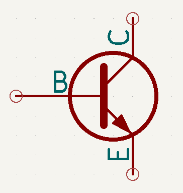
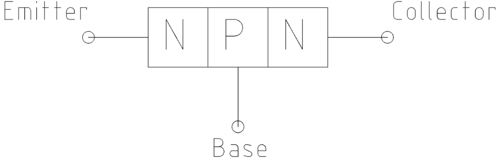
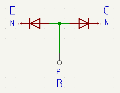
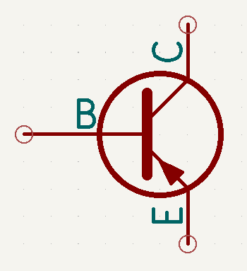
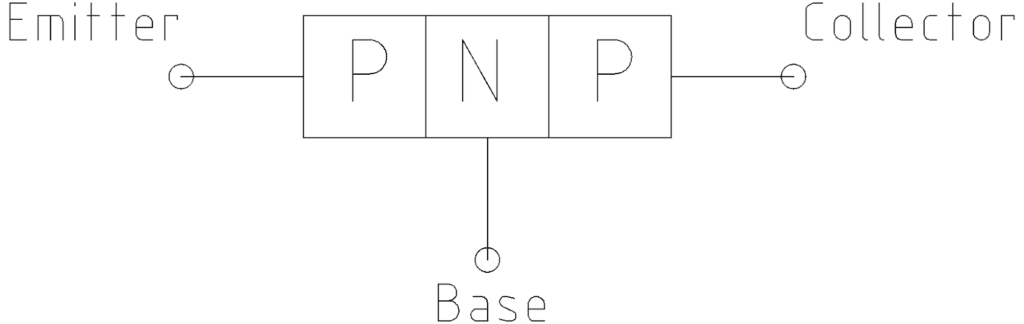
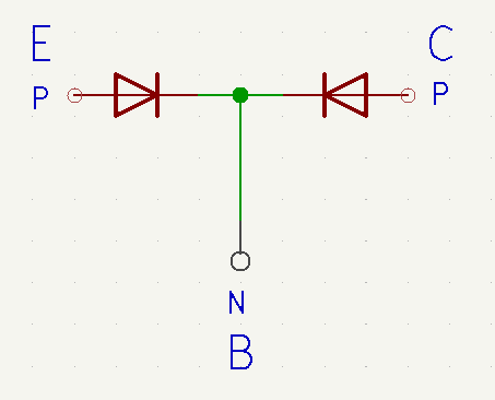
A transistor is a three-layer semiconductor device. It is basically made up of two PN-junction diodes connected back-to-back. See the illustration above. The diodes share a common region or terminal called the base. With this information, you can easily test if a transistor is good or bad.
Additionally, in order for a transistor to do amplification, the Base-Emitter junction should be forward, while the Base-Collector reverse biased. Note that the Base-Emitter junction is more heavily doped than the Base-Collector junction. With this, the base current can be amplified a hundred times more than the collector current.
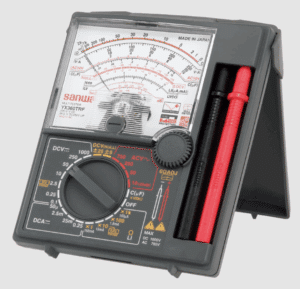
For an Analog Meter
Image courtesy of Sanwa meters Japan
Remember, the polarity of your probes determine the actual biases you apply to the BJT.
Testing either the Emitter-Base or Collector-Base Junction
If you know the pinout of your transistor, test the Emitter-Base, and then the Base-Collector junction using a multimeter. You can use the Ohmeter. If you don’t know the pinout, you can do trial and error.
The Emitter-Base in forward bias will have a low resistance while having high resistance in reverse.
Similarly, the Collector-Base in forward bias will have a low resistance while having high resistance in reverse.
Find the two back to back diodes. If any of the characteristics of a diode fail on your test, your transistor is likely bad.
Finding the Collector and Emitter Pins
Having known the two diode junctions and the base pin from the previous steps, you are left to find which are the Collector and Emitter pins.
Measure the resistance between the base and the other two pins.
The emitter usually shows slightly lower resistance than the collector due to heavier doping.
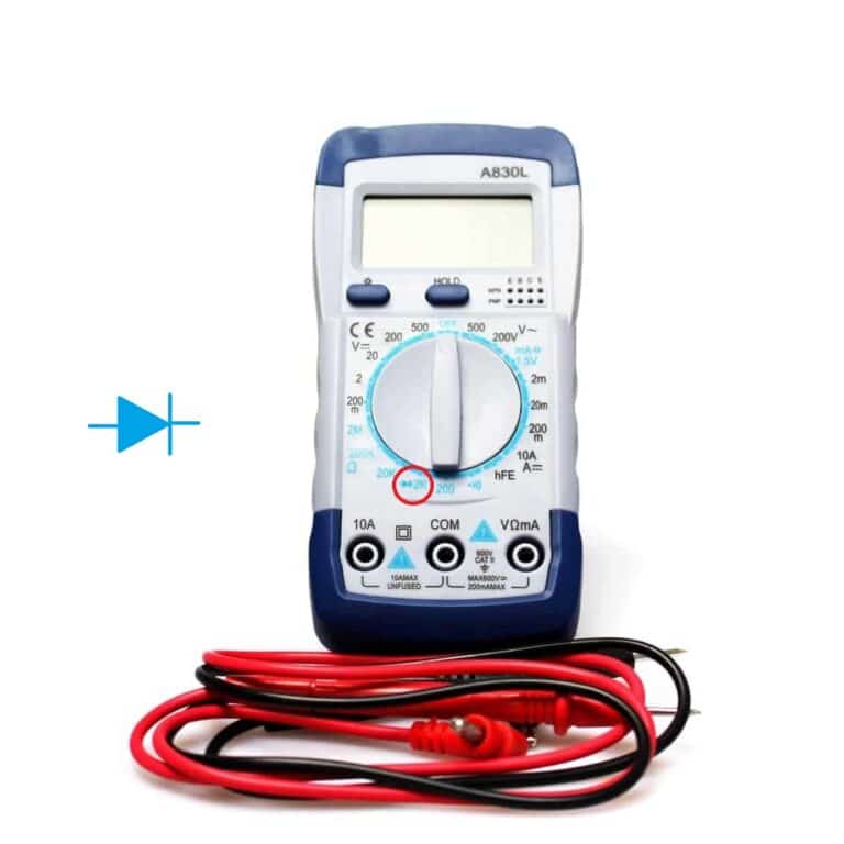
For a Meter with a Diode Test Function
Find the diode test function on your DMM.
It’s easier to test a BJT using the diode test function of a multimeter.
Find the Emitter-Base and Base-Collector forward bias diode junctions. Since these are forward bias junctions, you should see a voltage drop of about 0.5V – 0.7V.
To identify which is Collector and which is Emitter: The pin tapped showing a higher voltage drop (~0.65–0.7V) is the emitter while the pin showing lower voltage drop (~0.55–0.6V) is the collector.