Have you run out of PWM pins on your microcontroller? Are you worried about component costs and can’t afford to add another chip with PWM functionality on your BOM? Worry no more as there’s a way to turn your digital I/O pins into PWM.
Introduction
Pulse Width Modulation (or PWM for short) is a clever way to modulate the output power delivered by your components or peripherals. Imagine you have a power LED with a transistor driver that you can turn on to maximum brightness once you apply an output high on your microcontroller. If you are on a power budget and want to keep the size of your power supply as small as possible, implementing PWM on this power LED is a smart choice. However, if your PWM ports have all been used for other applications such as motor control, or voltage regulation, you’re only option is to convert your digital IO pin to PWM using code.
What is PWM?
As the name implies, PWM modifies the pulse width of a signal. This pulse width is what is known as the high time of the signal. The rest of it is the low time of the signal. The ratio between the high time and the low time of the signal is the percent Duty Cycle. In mathematical form:

Here is a diagram giving an example of 2 different PWM waveforms and their Duty Cycles
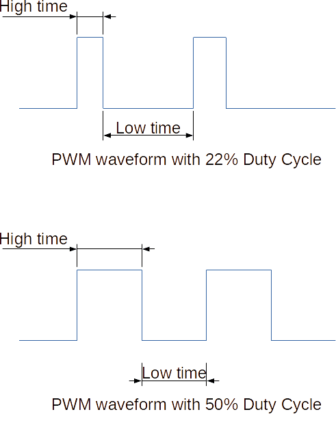
Along with the Duty Cycle, you should choose an appropriate Frequency where your PWM signal will operate, and a Resolution to scale up how many bits you can reserve for a full scale 0% to 100% Duty Cycle range. The Frequency will depend on your application. If it’s an LED, for example, a couple of hundreds of Hz should suffice. Low Duty Cycles in this Frequency range should be negligible to the human eye. The Resolution will depend on what your PWM peripheral can handle. Higher PWM resolutions tend to have smoother transitions between Duty Cycle values but can come at a price when choosing microcontrollers.
As you can see it’s not a very complicated operation. With this info, you can generate any PWM signal knowing its Frequency, Duty Cycle, and Resolution by only using Digital I/O pins.
A Microcontrollers PWM Peripheral
Most microcontrollers implement PWM as a peripheral. This means that the PWM works independently, and does not steal precious instruction cycles needed by your MCU. Some microcontrollers integrate PWM functionality with their timer modules. As an example, look at the PWM controller being employed on an ATMega328P (or the Arduino UNO)
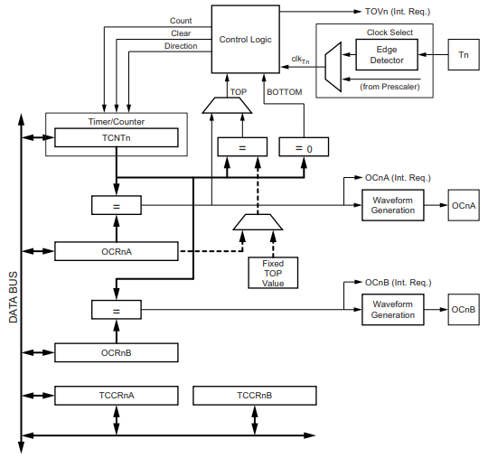
Here, the Timer/Counter module implements an OC or Output Compare module. The OC module is responsible for generating a digital waveform pattern based on its Output Compare Register (OCR) versus the Timer Count Register (TCNT). With this functionality, a PWM waveform can be generated, turning this Timer module into a PWM generator.
Software PWM Implementation
If you’ve used up all of your microcontroller’s PWM peripheral, you can implement what is called Software PWM. Software PWM as its name implies mimics the output of a standard PWM peripheral. The only difference is that with Software PWM, some other resources of the MCU will be used.
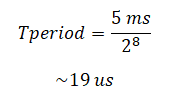
To start with, decide on your PWM’s resolution and frequency. This in turn will give you a hint on what kind of Timer to use. The formula to get your timer’s period is:

For example, if you want a PWM with a frequency of 200 Hz and a resolution of 8 bits, your target is to get a timer period of:
If you have a system clock running at 16 MHz, you can load the timer pre-load register with:
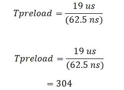
Since we have an 8-bit PWM resolution, it means we can traverse all 256 duty cycle steps from 0% to 100%. We’ll load 255 on a counter variable at every start of our PWM cycle and start with the output high. Next, we’ll decrement this variable on every timer interrupt (that actually coincides with the resolution), and compare it with our chosen duty cycle value. If it matches our duty cycle then we’ll pull the output low. When it reaches 0, we’ll start all over again.
Make a Sample Code
This is a code for the Arduino UNO that implements software PWM:
					// find timer counter value for a
// 19us resolution time
// with 16MHz or 62.5ns clock
// we have = 304 counter value

const uint16_t tmr1_cmp = 304;

uint8_t duty_cycle, DC_cnt;

void setup() {

  // put your setup code here, to run once:
  pinMode(LED_BUILTIN, OUTPUT);

  // reset T1 register
  TCCR1A = 0;

  // set prescaler to 1;
  TCCR1B &= ~(1 << CS12);
  TCCR1B &= ~(1 << CS11);
  TCCR1B |= (1 << CS10);

  // load timer and cmpare register
  TCNT1 = 0;
  OCR1A = tmr1_cmp;

  // load duty cycle 0 - 256 (8-bit resoltion)
  // 0 = 100%
  // 255 = 0%
  duty_cycle = 100; // 39% DC
  DC_cnt = 255;

  // enable compare interrupt
  TIMSK1 |= (1 << OCIE1A);

  // enable global interrupt
  sei();

}

void loop() {
  // put your main code here, to run repeatedly:1
}

ISR(TIMER1_COMPA_vect) {

  TCNT1 = 0;    // reset counter value to be able to re-implement ISR again
  DC_cnt--;     // decrement duty cycle count

  if(DC_cnt == 0)         // start of PWM waveform
  {
    if(duty_cycle < 255)  // Duty_cycle must be less than 255, otherwsie DC is 0%
    {
      digitalWrite(LED_BUILTIN, HIGH);  // pull pin high
      DC_cnt = 255;                     // reset DC counter
    }
  }
  else
  {
    if(duty_cycle == DC_cnt)            // our intended DC
      digitalWrite(LED_BUILTIN, LOW);   // pull pin low to implement pwm
  }

}
The code requires register-level access to your timer and will use its ISR. Note that you’ll not be able to use certain resources in the Arduino environment if the timer you chose coincides with a certain function. See the table below about shared resources when it comes to timers.
| Timer Name | Arduino Function |
|---|---|
| Timer 0 | millis(), micros(), delay(), analogWrite of pins 5 and 6 |
| Timer 1 | analogWrite of pins 9 and 10, servo function |
| Timer 2 | analogWrite of pins 3 and 11, tone function |
Resources used by timers in the Arduino environment
Summary
Implementing PWM on a digital I/O pin on your microcontroller is easy although it may require additional resources such as an interrupt vector, a timer, and additional variables. Once you get familiar with the algorithm, you should be able to apply software PWM to any architecture.
