Continue learning how to write code for your STM32 device in STM32Cube IDE using UART in normal, interrupt mode, and DMA mode.
INtroduction
Part 1 of the STM32 UART Interrupt & DMA blog discussed setting up the UART peripheral in different modes in STM32Cube IDE. These modes include polling mode, interrupt mode, and DMA mode. Each mode has distinct advantages and disadvantages and can use your STM32’s resources differently. Here, you’ll learn how to code each mode after successfully setting them up using STM32CubeMX.
UART in Blocking Mode
You can code UART in the simplest form in blocking mode by using the HAL_UART_Receive() and HAL_UART_Transmit() API where:
HAL_UART_Receive(UART_HandleTypeDef *huart, uint8_t *pData, uint16_t Size, uint32_t Timeout)
* @param huart Pointer to a UART_HandleTypeDef structure that contains
* the configuration information for the specified UART module.
* @param pData Pointer to data buffer (u8 or u16 data elements).
* @param Size Amount of data elements (u8 or u16) to be sent
* @param Timeout Timeout duration
* @retval HAL
HAL_UART_Transmit(&huart1, tx_buffer, sizeof(tx_buffer), 10);
* @param huart Pointer to a UART_HandleTypeDef structure that contains
* the configuration information for the specified UART module.
* @param pData Pointer to data buffer (u8 or u16 data elements).
* @param Size Amount of data elements (u8 or u16) to be sent
* @param Timeout Timeout duration
* @retval HAL status
Below is a sample code that waits for 10 packets from a user (it waits forever). After receiving the 10 packets, it proceeds to notify the user that it received them. The packets are saved in an rx_buffer array.
					/* USER CODE BEGIN Header */
/**
  ******************************************************************************
  * @file           : main.c
  * @brief          : Main program body
  ******************************************************************************
  * @attention
  *
  * Copyright (c) 2024 STMicroelectronics.
  * All rights reserved.
  *
  * This software is licensed under terms that can be found in the LICENSE file
  * in the root directory of this software component.
  * If no LICENSE file comes with this software, it is provided AS-IS.
  *
  ******************************************************************************
  */
/* USER CODE END Header */
/* Includes ------------------------------------------------------------------*/
#include "main.h"

/* Private includes ----------------------------------------------------------*/
/* USER CODE BEGIN Includes */

/* USER CODE END Includes */

/* Private typedef -----------------------------------------------------------*/
/* USER CODE BEGIN PTD */

/* USER CODE END PTD */

/* Private define ------------------------------------------------------------*/
/* USER CODE BEGIN PD */

/* USER CODE END PD */

/* Private macro -------------------------------------------------------------*/
/* USER CODE BEGIN PM */

/* USER CODE END PM */

/* Private variables ---------------------------------------------------------*/
UART_HandleTypeDef huart1;

/* USER CODE BEGIN PV */

/* USER CODE END PV */

/* Private function prototypes -----------------------------------------------*/
void SystemClock_Config(void);
static void MX_GPIO_Init(void);
static void MX_USART1_UART_Init(void);
/* USER CODE BEGIN PFP */

/* USER CODE END PFP */

/* Private user code ---------------------------------------------------------*/
/* USER CODE BEGIN 0 */

/* USER CODE END 0 */

/**
  * @brief  The application entry point.
  * @retval int
  */
int main(void)
{

  /* USER CODE BEGIN 1 */

  /* USER CODE END 1 */

  /* MCU Configuration--------------------------------------------------------*/

  /* Reset of all peripherals, Initializes the Flash interface and the Systick. */
  HAL_Init();

  /* USER CODE BEGIN Init */

  /* USER CODE END Init */

  /* Configure the system clock */
  SystemClock_Config();

  /* USER CODE BEGIN SysInit */

  /* USER CODE END SysInit */

  /* Initialize all configured peripherals */
  MX_GPIO_Init();
  MX_USART1_UART_Init();
  /* USER CODE BEGIN 2 */

  HAL_StatusTypeDef ret;
  uint8_t rx_buffer[10];
  uint8_t tx_buffer[] = "Received 10 UART Packets\r\n";


  /* USER CODE END 2 */

  /* Infinite loop */
  /* USER CODE BEGIN WHILE */
  while (1)
  {
	  // receive 10 UART packets in blocking mode
	  ret = HAL_UART_Receive(&huart1, rx_buffer, sizeof(rx_buffer), HAL_MAX_DELAY);
	  if(ret == HAL_OK)
	  {
		  HAL_UART_Transmit(&huart1, tx_buffer, sizeof(tx_buffer), 10);
	  }

    /* USER CODE END WHILE */
    /* USER CODE BEGIN 3 */
  }
  /* USER CODE END 3 */
}

/**
  * @brief System Clock Configuration
  * @retval None
  */
void SystemClock_Config(void)
{
  RCC_OscInitTypeDef RCC_OscInitStruct = {0};
  RCC_ClkInitTypeDef RCC_ClkInitStruct = {0};

  /** Configure the main internal regulator output voltage
  */
  __HAL_RCC_PWR_CLK_ENABLE();
  __HAL_PWR_VOLTAGESCALING_CONFIG(PWR_REGULATOR_VOLTAGE_SCALE1);

  /** Initializes the RCC Oscillators according to the specified parameters
  * in the RCC_OscInitTypeDef structure.
  */
  RCC_OscInitStruct.OscillatorType = RCC_OSCILLATORTYPE_HSE;
  RCC_OscInitStruct.HSEState = RCC_HSE_ON;
  RCC_OscInitStruct.PLL.PLLState = RCC_PLL_ON;
  RCC_OscInitStruct.PLL.PLLSource = RCC_PLLSOURCE_HSE;
  RCC_OscInitStruct.PLL.PLLM = 12;
  RCC_OscInitStruct.PLL.PLLN = 96;
  RCC_OscInitStruct.PLL.PLLP = RCC_PLLP_DIV2;
  RCC_OscInitStruct.PLL.PLLQ = 4;
  if (HAL_RCC_OscConfig(&RCC_OscInitStruct) != HAL_OK)
  {
    Error_Handler();
  }

  /** Initializes the CPU, AHB and APB buses clocks
  */
  RCC_ClkInitStruct.ClockType = RCC_CLOCKTYPE_HCLK|RCC_CLOCKTYPE_SYSCLK
                              |RCC_CLOCKTYPE_PCLK1|RCC_CLOCKTYPE_PCLK2;
  RCC_ClkInitStruct.SYSCLKSource = RCC_SYSCLKSOURCE_PLLCLK;
  RCC_ClkInitStruct.AHBCLKDivider = RCC_SYSCLK_DIV1;
  RCC_ClkInitStruct.APB1CLKDivider = RCC_HCLK_DIV2;
  RCC_ClkInitStruct.APB2CLKDivider = RCC_HCLK_DIV1;

  if (HAL_RCC_ClockConfig(&RCC_ClkInitStruct, FLASH_LATENCY_3) != HAL_OK)
  {
    Error_Handler();
  }
}

/**
  * @brief USART1 Initialization Function
  * @param None
  * @retval None
  */
static void MX_USART1_UART_Init(void)
{

  /* USER CODE BEGIN USART1_Init 0 */

  /* USER CODE END USART1_Init 0 */

  /* USER CODE BEGIN USART1_Init 1 */

  /* USER CODE END USART1_Init 1 */
  huart1.Instance = USART1;
  huart1.Init.BaudRate = 115200;
  huart1.Init.WordLength = UART_WORDLENGTH_8B;
  huart1.Init.StopBits = UART_STOPBITS_1;
  huart1.Init.Parity = UART_PARITY_NONE;
  huart1.Init.Mode = UART_MODE_TX_RX;
  huart1.Init.HwFlowCtl = UART_HWCONTROL_NONE;
  huart1.Init.OverSampling = UART_OVERSAMPLING_16;
  if (HAL_UART_Init(&huart1) != HAL_OK)
  {
    Error_Handler();
  }
  /* USER CODE BEGIN USART1_Init 2 */

  /* USER CODE END USART1_Init 2 */

}

/**
  * @brief GPIO Initialization Function
  * @param None
  * @retval None
  */
static void MX_GPIO_Init(void)
{
  GPIO_InitTypeDef GPIO_InitStruct = {0};
/* USER CODE BEGIN MX_GPIO_Init_1 */
/* USER CODE END MX_GPIO_Init_1 */

  /* GPIO Ports Clock Enable */
  __HAL_RCC_GPIOC_CLK_ENABLE();
  __HAL_RCC_GPIOH_CLK_ENABLE();
  __HAL_RCC_GPIOA_CLK_ENABLE();

  /*Configure GPIO pin Output Level */
  HAL_GPIO_WritePin(LED_GPIO_Port, LED_Pin, GPIO_PIN_RESET);

  /*Configure GPIO pin : LED_Pin */
  GPIO_InitStruct.Pin = LED_Pin;
  GPIO_InitStruct.Mode = GPIO_MODE_OUTPUT_PP;
  GPIO_InitStruct.Pull = GPIO_NOPULL;
  GPIO_InitStruct.Speed = GPIO_SPEED_FREQ_LOW;
  HAL_GPIO_Init(LED_GPIO_Port, &GPIO_InitStruct);

/* USER CODE BEGIN MX_GPIO_Init_2 */
/* USER CODE END MX_GPIO_Init_2 */
}

/* USER CODE BEGIN 4 */

/* USER CODE END 4 */

/**
  * @brief  This function is executed in case of error occurrence.
  * @retval None
  */
void Error_Handler(void)
{
  /* USER CODE BEGIN Error_Handler_Debug */
  /* User can add his own implementation to report the HAL error return state */
  __disable_irq();
  while (1)
  {
  }
  /* USER CODE END Error_Handler_Debug */
}

#ifdef  USE_FULL_ASSERT
/**
  * @brief  Reports the name of the source file and the source line number
  *         where the assert_param error has occurred.
  * @param  file: pointer to the source file name
  * @param  line: assert_param error line source number
  * @retval None
  */
void assert_failed(uint8_t *file, uint32_t line)
{
  /* USER CODE BEGIN 6 */
  /* User can add his own implementation to report the file name and line number,
     ex: printf("Wrong parameters value: file %s on line %d\r\n", file, line) */
  /* USER CODE END 6 */
}
#endif /* USE_FULL_ASSERT */
The main code of interest is below. A UART rx_buffer is defined along with a tx_buffer. In the while loop, the UART receive API (HAL_UART_Receive()) is started. Once this is started, it will be in blocking mode to wait until a timeout finishes or until the number of defined packets have been reached (forever wait).
					  /* USER CODE BEGIN 2 */

  HAL_StatusTypeDef ret;
  uint8_t rx_buffer[10];
  uint8_t tx_buffer[] = "Received 10 UART Packets\r\n";


  /* USER CODE END 2 */

  /* Infinite loop */
  /* USER CODE BEGIN WHILE */
  while (1)
  {
	  // receive 10 UART packets in blocking mode
	  ret = HAL_UART_Receive(&huart1, rx_buffer, sizeof(rx_buffer), HAL_MAX_DELAY);
	  if(ret == HAL_OK)
	  {
		  HAL_UART_Transmit(&huart1, tx_buffer, sizeof(tx_buffer), 10);
	  }

    /* USER CODE END WHILE */
    /* USER CODE BEGIN 3 */
  }
  /* USER CODE END 3 */
On demo, a user inputs UART data by pressing keys on the keyboard, and it is shown in real-time on the Status area (TXD) on the right on the serial window. When the presses reach ten counts (or packets), the UART transmit function continues code to displays it on the screen.
UART in Interrupt Mode
UART in interrupt mode is more efficient since you can run other code while waiting for all your packets to finish. You may want to check Interrupt Service Routine: Best Practices before continuing to have a primer on using interrupts on a microcontroller. The whole code is listed below. UART in interrupt mode uses the HAL_UART_Receive_IT() and HAL_UART_Transmit_IT() API functions.
					/* USER CODE BEGIN Header */
/**
  ******************************************************************************
  * @file           : main.c
  * @brief          : Main program body
  ******************************************************************************
  * @attention
  *
  * Copyright (c) 2024 STMicroelectronics.
  * All rights reserved.
  *
  * This software is licensed under terms that can be found in the LICENSE file
  * in the root directory of this software component.
  * If no LICENSE file comes with this software, it is provided AS-IS.
  *
  ******************************************************************************
  */
/* USER CODE END Header */
/* Includes ------------------------------------------------------------------*/
#include "main.h"

/* Private includes ----------------------------------------------------------*/
/* USER CODE BEGIN Includes */

/* USER CODE END Includes */

/* Private typedef -----------------------------------------------------------*/
/* USER CODE BEGIN PTD */

/* USER CODE END PTD */

/* Private define ------------------------------------------------------------*/
/* USER CODE BEGIN PD */

/* USER CODE END PD */

/* Private macro -------------------------------------------------------------*/
/* USER CODE BEGIN PM */

/* USER CODE END PM */

/* Private variables ---------------------------------------------------------*/
UART_HandleTypeDef huart1;

/* USER CODE BEGIN PV */
volatile uint8_t uart_rx_flag;
/* USER CODE END PV */

/* Private function prototypes -----------------------------------------------*/
void SystemClock_Config(void);
static void MX_GPIO_Init(void);
static void MX_USART1_UART_Init(void);
/* USER CODE BEGIN PFP */

/* USER CODE END PFP */

/* Private user code ---------------------------------------------------------*/
/* USER CODE BEGIN 0 */

/* USER CODE END 0 */

/**
  * @brief  The application entry point.
  * @retval int
  */
int main(void)
{

  /* USER CODE BEGIN 1 */

  /* USER CODE END 1 */

  /* MCU Configuration--------------------------------------------------------*/

  /* Reset of all peripherals, Initializes the Flash interface and the Systick. */
  HAL_Init();

  /* USER CODE BEGIN Init */

  /* USER CODE END Init */

  /* Configure the system clock */
  SystemClock_Config();

  /* USER CODE BEGIN SysInit */

  /* USER CODE END SysInit */

  /* Initialize all configured peripherals */
  MX_GPIO_Init();
  MX_USART1_UART_Init();
  /* USER CODE BEGIN 2 */

  uint8_t rx_buffer[10];
  uint8_t tx_buffer1[] = "Running Code\r\n";
  uint8_t tx_buffer2[] = "Received 10 UART Packets\r\n";

  // for receive interrupt state machine
  typedef enum uart_rx_mode_tag {
	  start_rx,
	  wait_rx_it,
  }uart_rx_mode_t;

  uart_rx_mode_t uart_rx_mode;
  uart_rx_mode = start_rx;

  /* USER CODE END 2 */

  /* Infinite loop */
  /* USER CODE BEGIN WHILE */
  while (1)
  {
	  switch (uart_rx_mode) {
		case start_rx:
			// start to receive 10 UART packets in non-blocking, interrupt mode
			HAL_UART_Receive_IT(&huart1, rx_buffer, sizeof(rx_buffer));
			// next state
			uart_rx_mode = wait_rx_it;
			break;

		case wait_rx_it:
			// check uart_flag
			if(uart_rx_flag)
			{
				// received all the packets
				HAL_UART_Transmit(&huart1, tx_buffer2, sizeof(tx_buffer2), 10);
				// reset flag to 0
				uart_rx_flag = 0;
				// next rx_state
				uart_rx_mode = start_rx;

			}else{
				// same rx_state
				// proceed to run other code to make things efficient
				HAL_UART_Transmit(&huart1, tx_buffer1, sizeof(tx_buffer1), 10);
				// delay for demonstration
				HAL_Delay(1000);
			}
			break;
		default:
			break;
	}

    /* USER CODE END WHILE */

    /* USER CODE BEGIN 3 */
  }
  /* USER CODE END 3 */
}

/**
  * @brief System Clock Configuration
  * @retval None
  */
void SystemClock_Config(void)
{
  RCC_OscInitTypeDef RCC_OscInitStruct = {0};
  RCC_ClkInitTypeDef RCC_ClkInitStruct = {0};

  /** Configure the main internal regulator output voltage
  */
  __HAL_RCC_PWR_CLK_ENABLE();
  __HAL_PWR_VOLTAGESCALING_CONFIG(PWR_REGULATOR_VOLTAGE_SCALE1);

  /** Initializes the RCC Oscillators according to the specified parameters
  * in the RCC_OscInitTypeDef structure.
  */
  RCC_OscInitStruct.OscillatorType = RCC_OSCILLATORTYPE_HSE;
  RCC_OscInitStruct.HSEState = RCC_HSE_ON;
  RCC_OscInitStruct.PLL.PLLState = RCC_PLL_ON;
  RCC_OscInitStruct.PLL.PLLSource = RCC_PLLSOURCE_HSE;
  RCC_OscInitStruct.PLL.PLLM = 12;
  RCC_OscInitStruct.PLL.PLLN = 96;
  RCC_OscInitStruct.PLL.PLLP = RCC_PLLP_DIV2;
  RCC_OscInitStruct.PLL.PLLQ = 4;
  if (HAL_RCC_OscConfig(&RCC_OscInitStruct) != HAL_OK)
  {
    Error_Handler();
  }

  /** Initializes the CPU, AHB and APB buses clocks
  */
  RCC_ClkInitStruct.ClockType = RCC_CLOCKTYPE_HCLK|RCC_CLOCKTYPE_SYSCLK
                              |RCC_CLOCKTYPE_PCLK1|RCC_CLOCKTYPE_PCLK2;
  RCC_ClkInitStruct.SYSCLKSource = RCC_SYSCLKSOURCE_PLLCLK;
  RCC_ClkInitStruct.AHBCLKDivider = RCC_SYSCLK_DIV1;
  RCC_ClkInitStruct.APB1CLKDivider = RCC_HCLK_DIV2;
  RCC_ClkInitStruct.APB2CLKDivider = RCC_HCLK_DIV1;

  if (HAL_RCC_ClockConfig(&RCC_ClkInitStruct, FLASH_LATENCY_3) != HAL_OK)
  {
    Error_Handler();
  }
}

/**
  * @brief USART1 Initialization Function
  * @param None
  * @retval None
  */
static void MX_USART1_UART_Init(void)
{

  /* USER CODE BEGIN USART1_Init 0 */

  /* USER CODE END USART1_Init 0 */

  /* USER CODE BEGIN USART1_Init 1 */

  /* USER CODE END USART1_Init 1 */
  huart1.Instance = USART1;
  huart1.Init.BaudRate = 115200;
  huart1.Init.WordLength = UART_WORDLENGTH_8B;
  huart1.Init.StopBits = UART_STOPBITS_1;
  huart1.Init.Parity = UART_PARITY_NONE;
  huart1.Init.Mode = UART_MODE_TX_RX;
  huart1.Init.HwFlowCtl = UART_HWCONTROL_NONE;
  huart1.Init.OverSampling = UART_OVERSAMPLING_16;
  if (HAL_UART_Init(&huart1) != HAL_OK)
  {
    Error_Handler();
  }
  /* USER CODE BEGIN USART1_Init 2 */

  /* USER CODE END USART1_Init 2 */

}

/**
  * @brief GPIO Initialization Function
  * @param None
  * @retval None
  */
static void MX_GPIO_Init(void)
{
  GPIO_InitTypeDef GPIO_InitStruct = {0};
/* USER CODE BEGIN MX_GPIO_Init_1 */
/* USER CODE END MX_GPIO_Init_1 */

  /* GPIO Ports Clock Enable */
  __HAL_RCC_GPIOC_CLK_ENABLE();
  __HAL_RCC_GPIOH_CLK_ENABLE();
  __HAL_RCC_GPIOA_CLK_ENABLE();

  /*Configure GPIO pin Output Level */
  HAL_GPIO_WritePin(LED_GPIO_Port, LED_Pin, GPIO_PIN_RESET);

  /*Configure GPIO pin : LED_Pin */
  GPIO_InitStruct.Pin = LED_Pin;
  GPIO_InitStruct.Mode = GPIO_MODE_OUTPUT_PP;
  GPIO_InitStruct.Pull = GPIO_NOPULL;
  GPIO_InitStruct.Speed = GPIO_SPEED_FREQ_LOW;
  HAL_GPIO_Init(LED_GPIO_Port, &GPIO_InitStruct);

/* USER CODE BEGIN MX_GPIO_Init_2 */
/* USER CODE END MX_GPIO_Init_2 */
}

/* USER CODE BEGIN 4 */
/**
  * @brief  Rx Transfer completed callbacks.
  * @param  huart  Pointer to a UART_HandleTypeDef structure that contains
  *                the configuration information for the specified UART module.
  * @retval None
  */
void HAL_UART_RxCpltCallback(UART_HandleTypeDef *huart)
{
  /* Prevent unused argument(s) compilation warning */
  UNUSED(huart);
  uart_rx_flag = 1;
  /* NOTE: This function should not be modified, when the callback is needed,
           the HAL_UART_RxCpltCallback could be implemented in the user file
   */
}

/* USER CODE END 4 */

/**
  * @brief  This function is executed in case of error occurrence.
  * @retval None
  */
void Error_Handler(void)
{
  /* USER CODE BEGIN Error_Handler_Debug */
  /* User can add his own implementation to report the HAL error return state */
  __disable_irq();
  while (1)
  {
  }
  /* USER CODE END Error_Handler_Debug */
}

#ifdef  USE_FULL_ASSERT
/**
  * @brief  Reports the name of the source file and the source line number
  *         where the assert_param error has occurred.
  * @param  file: pointer to the source file name
  * @param  line: assert_param error line source number
  * @retval None
  */
void assert_failed(uint8_t *file, uint32_t line)
{
  /* USER CODE BEGIN 6 */
  /* User can add his own implementation to report the file name and line number,
     ex: printf("Wrong parameters value: file %s on line %d\r\n", file, line) */
  /* USER CODE END 6 */
}
#endif /* USE_FULL_ASSERT */
Here is the code explanation: Since you are now working in interrupt mode, it’s best to use a status flag when a UART interrupt occurs.
					/* USER CODE BEGIN PV */
volatile uint8_t uart_rx_flag;
/* USER CODE END PV */
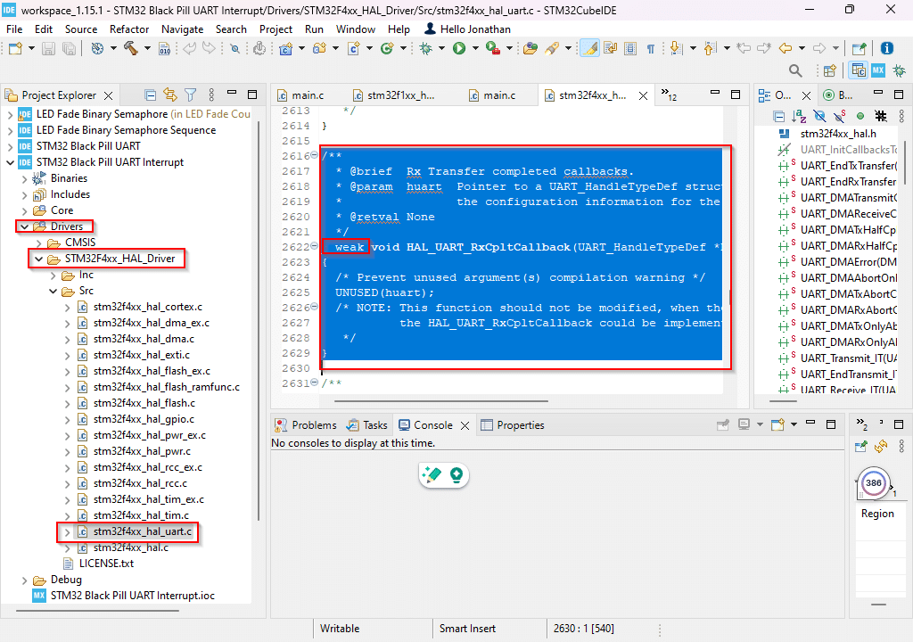
To easily integrate the UART RX ISR code in your main.c file, find the UART driver source code in the left-hand Project Explorer pane. You should see stm32f4xx_hal_uart.c inside a HAL Driver folder. Copy the __weak HAL_UART_RxCpltCallback() function to an empty code block on your main.c file making sure you take out the __weak directive.
set the volatile global uart_rx_flag here to 1 to indicate that the UART RX interrupt occured.
					/* USER CODE BEGIN 4 */
/**
  * @brief  Rx Transfer completed callbacks.
  * @param  huart  Pointer to a UART_HandleTypeDef structure that contains
  *                the configuration information for the specified UART module.
  * @retval None
  */
void HAL_UART_RxCpltCallback(UART_HandleTypeDef *huart)
{
  /* Prevent unused argument(s) compilation warning */
  UNUSED(huart);
  uart_rx_flag = 1;
  /* NOTE: This function should not be modified, when the callback is needed,
           the HAL_UART_RxCpltCallback could be implemented in the user file
   */
}

/* USER CODE END 4 */
The main code of interest for receiving in interrupt mode is below. Like the process before, transmit and receive buffer/s are used. Here a state machine starts the UART RX INT then waits for the RX INT whilst also being capable of running other code. The UART RX INT happens when all UART packets are received. Note, though, that each byte received can trigger other UART related interrupts that may be handled internally by the API. After this, the program displays that the UART RX INT event happened. An rx_buffer array receives all the packet.
					  /* USER CODE BEGIN 2 */

  uint8_t rx_buffer[10];
  uint8_t tx_buffer1[] = "Running Code\r\n";
  uint8_t tx_buffer2[] = "Received 10 UART Packets\r\n";

  // for receive interrupt state machine
  typedef enum uart_rx_mode_tag {
	  start_rx,
	  wait_rx_it,
  }uart_rx_mode_t;

  uart_rx_mode_t uart_rx_mode;
  uart_rx_mode = start_rx;

  /* USER CODE END 2 */

  /* Infinite loop */
  /* USER CODE BEGIN WHILE */
  while (1)
  {
	  switch (uart_rx_mode) {
		case start_rx:
			// start to receive 10 UART packets in non-blocking, interrupt mode
			HAL_UART_Receive_IT(&huart1, rx_buffer, sizeof(rx_buffer));
			// next state
			uart_rx_mode = wait_rx_it;
			break;

		case wait_rx_it:
			// check uart_flag
			if(uart_rx_flag)
			{
				// received all the packets
				HAL_UART_Transmit(&huart1, tx_buffer2, sizeof(tx_buffer2), 10);
				// reset flag to 0
				uart_rx_flag = 0;
				// next rx_state
				uart_rx_mode = start_rx;

			}else{
				// same rx_state
				// proceed to run other code to make things efficient
				HAL_UART_Transmit(&huart1, tx_buffer1, sizeof(tx_buffer1), 10);
				// delay for demonstration
				HAL_Delay(1000);
			}
			break;
		default:
			break;
	}

    /* USER CODE END WHILE */
That is how STM32Cube IDE implements a UART interrupt. The next part will discuss the most efficient and fastest way to implement UART which is using DMA (Direct Memory Access).
SHOP THIS PROJECT
-
Sale!

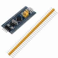
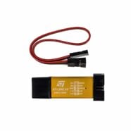
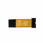
ST-Link V2 Mini In-Circuit Programmer and Debugger for STM8 / STM32
$31.95Original price was: $31.95.$16.95Current price is: $16.95. Read more