Introduction
This tutorial details the 5 Way Tactile Navigation Button Module, how it functions and the method of building a simple project using the 5 Way Tactile Navigation Button Module and an Arduino.
5 Way Tactile Navigation Button Module
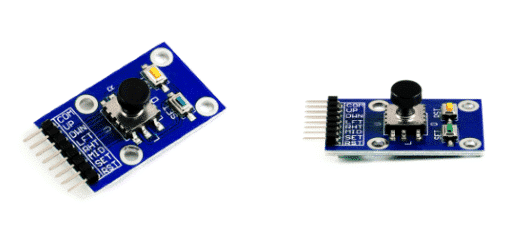
The 5 Way Tactile Navigation Button Module has seven button outputs and is used for the navigation control of model toys and projects.
Figure 1 shows the image of the 5 Way Tactile Navigation Button Module.
Pin Out
The APDS-9960 has six pins.
| Pin | Description |
|---|---|
| COM | Common Pin |
| UP | Up |
| DWN | Down |
| LFT | Left |
| RHT | Right |
| MID | Middle |
| SET | Set |
| RST | Reset |
How it Works
The 5 Way Tactile Navigation Button Module is composed of a 5-way tactile switch made like a joystick with two additional functional buttons. The module functions like standard buttons assembled in one compact and easy to use module.
Project - Arduino Navigation Key Monitor
This project will demonstrate the navigation button pressed in the serial monitor.
Components
- Arduino Uno Board
- 5 Way Tactile Navigation Button Module
- Jumper Wires
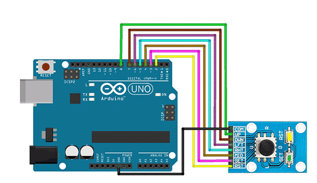
Wiring Diagram
The GY-ML8511 module pins are connected to the Arduino Uno board as follows:
| Module Pin | UNO Board Pin |
|---|---|
| COM | Ground |
| UP | 8 |
| DWN | 7 |
| LFT | 6 |
| RHT | 5 |
| MID | 4 |
| SET | 3 |
| RST | 2 |
Code
					//pin connections
#define buttonPin_RST 2
#define buttonPin_SET 3
#define buttonPin_MID 4
#define buttonPin_RHT 5
#define buttonPin_LFT 6
#define buttonPin_DWN 7
#define buttonPin_UP 8
void setup() {
  Serial.begin(9600);
  //pinmodes
  pinMode(buttonPin_RST, INPUT_PULLUP);
  pinMode(buttonPin_SET, INPUT_PULLUP);
  pinMode(buttonPin_MID, INPUT_PULLUP);
  pinMode(buttonPin_RHT, INPUT_PULLUP);
  pinMode(buttonPin_LFT, INPUT_PULLUP);
  pinMode(buttonPin_DWN, INPUT_PULLUP);
  pinMode(buttonPin_UP, INPUT_PULLUP);
}
void loop() {

  if (digitalRead(buttonPin_RST) == LOW) {
    Serial.println("Reset Pin Is Pressed.");
    delay(200);
  }
  if (digitalRead(buttonPin_SET) == LOW) {
    Serial.println("Set Pin Is Pressed.");
    delay(200);
  }
  if (digitalRead(buttonPin_MID) == LOW) {
    Serial.println("Middle Pin Is Pressed.");
    delay(200);
  }
  if (digitalRead(buttonPin_RHT) == LOW) {
    Serial.println("Right Pin Is Pressed.");
    delay(200);
  }
  if (digitalRead(buttonPin_LFT) == LOW) {
    Serial.println("Left Pin Is Pressed.");
    delay(200);
  }
  if (digitalRead(buttonPin_DWN) == LOW) {
    Serial.println("Down Pin Is Pressed.");
    delay(200);
  }
  if (digitalRead(buttonPin_UP) == LOW) {
    Serial.println("Up Pin Is Pressed.");
    delay(200);
  }
}
Project Test
Wire the components to the Arduino as demonstrated in the wiring diagram. Connect the Arduino to a PC and upload the program. Open the Serial Monitor in the Arduino IDE, and the navigation button pressed in the serial monitor will be displayed.