Introduction:
In this tutorial, we will learn about the KY-026 module, what is an infrared receiver LED and we will build a simple project using the KY-026 module and an Arduino.
Flame Sensor Module KY-026:
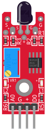
The KY-026 Module will be our main component for this tutorial. This module has an infrared receiver LED, and an LM393 differential comparator mounted on a breakout board with a potentiometer and several resistors. Figure 1 shows the module as seen in fritzing.
Pin Out:
The KY-026 module has four pins.
| Component Pin | Description |
|---|---|
| A0 | Analog output |
| G | Ground |
| (+) | +5V |
| D0 | Digital output |
What is a Infrared Receiver LED?
An infrared receiver LED is an electronic component that is sensitive to infrared light. It is commonly found in Fire Detection and Alarm Systems (FDAS) to detect fires because fires emit infrared radiation.
Project:
Arduino Infrared Detector:
After learning about the KY-026 module and the infrared receiver LED, it is now time to build a project using the module. Our project will get the analog and digital signals from the KY-026 module, display it on the serial monitor, and control the Arduino’s built-in LED.
Components:
For this project, we need the following components:
- Arduino Uno board (1 pc.)
- KY-026 Flame Sensor Module (1 pc.)
- Jumper wires
Wiring Diagram:
Figure 2 shows the connection between the Arduino Uno and the KY-026 Flame Sensor Module.
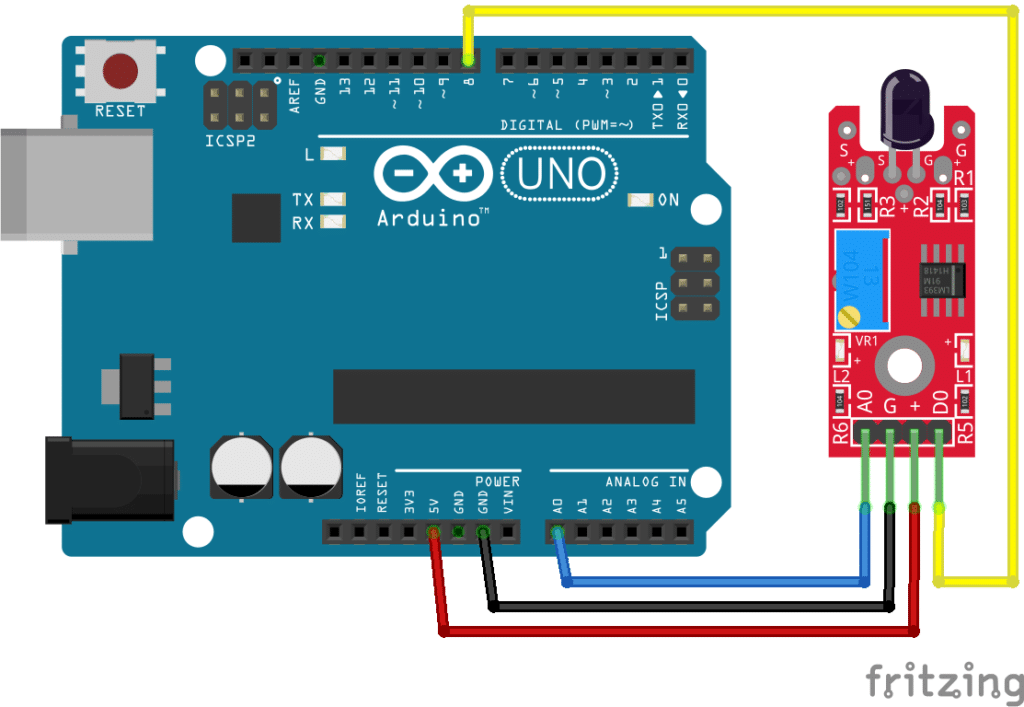
The KY-026 module pins are connected to the Arduino Uno board as follows:
| Component Pin | Description |
|---|---|
| A0 | A0 |
| G | GND |
| (+) | +5V |
| D0 | 8 |
Code:
Below is the Arduino sketch for our project. I have added comments to explain important parts of the code. Save the code as KY-026.ino and upload it to your Arduino board.
					// Arduino and KY-026 module
void setup ()
{
  pinMode (13, OUTPUT); // built-in LED pin set to output
  pinMode (8, INPUT);   // module digital output connected to Arduino pin 8
  Serial.begin(9600);   // initialize serial
}
void loop ()
{
  Serial.print("Analog pin: "); // display analog and digital values to serial
  Serial.print(analogRead(A0));
  Serial.print(" | Digital pin: ");
  if (digitalRead(8) == HIGH) {
    Serial.println("High");
    digitalWrite (13, HIGH); // if infrared value is higher than threshold , switch-On built-in LED
  }
  else {
    Serial.println("Low");
    digitalWrite (13, LOW);
  }
  delay(100); // wait 100 milliSeconds
}
Project Test:
Apply power to your Arduino Uno board and open the Serial Monitor in the Arduino IDE. Arduino will output the analog value sent by the module to the serial monitor. If the value reaches the threshold setpoint set by VR1, the built-in LED of the Arduino will also light-up. Adjust the threshold by turning VR1.