Introduction
In this tutorial, we will learn about the KY-038 module, how it works and we will build a simple project using the KY-038 module and an Arduino.
Microphone Sound Sensor Module KY-038
The KY-038 Module will be our main component for this tutorial. This module has a microphone, and an LM393 differential comparator mounted on a breakout board with a potentiometer and several resistors. Figure 1 shows the module as seen in fritzing.
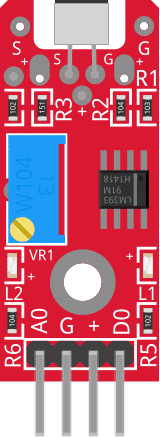
Pin Out
The KY-038 module has four pins.
| Pin | Description |
|---|---|
| A0 | Analog Output |
| G | Ground |
| (+) | +5V |
| D0 | Digital Output |
How It Works
A microphone converts the sound waves to analog signals which are then fed to a comparator circuit made-up by the LM393 circuit. The circuit compares the signal with a predetermined threshold set by VR1. If the sound intensity is greater than the threshold, it pulls the pin DO to HIGH, otherwise, the pin state is LOW. Meanwhile, the analog output at pin A0 depends on the loudness of the sound input.
Project - Ardunio Loudness Meter
After learning about the KY-038 module and how it works, it is now time to build a project using the module. Our project will get the analog and digital signals from the KY-038 module, display it on the serial monitor, and control the Arduino’s built-in LED.
Components
For this project, we need the following components:
- Arduino Uno board (1 pc.)
- KY-038 Microphone Sound Sensor Module (1 pc.)
- Jumper wires
Wiring Diagram
Figure 2 shows the connection between the Arduino Uno and the KY-038 Microphone Sound Sensor Module.
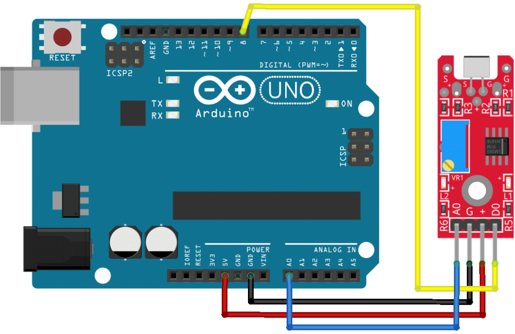
The KY-038 module pins are connected to the Arduino Uno board as follows:
| Component Pin | UNO Board Pin |
|---|---|
| A0 | A0 |
| G | Ground |
| (+) | +5V |
| D0 | 8 |
Code
					// Arduino and KY-038 module
void setup ()
{
pinMode (13, OUTPUT); // built-in LED pin set to output
pinMode (8, INPUT); // module digital output connected to Arduino pin 8
Serial.begin(9600); // initialize serial
}
void loop ()
{
// display analog and digital values to serial
Serial.print("Analog pin: ");
Serial.print(analogRead(A0));
Serial.print(" | Digital pin: ");
if (digitalRead(8) == HIGH) {
Serial.println("High");
digitalWrite (13, HIGH); // if module value is higher than threshold,
// switch-On built-in LED
}
else {
Serial.println("Low");
digitalWrite (13, LOW);
}
}
Project Test
Apply power to your Arduino Uno board and open the Serial Monitor in the Arduino IDE. Arduino will output the analog value sent by the module to the serial monitor. If the value reaches the threshold setpoint set by VR1, the built-in LED of the Arduino will also light-up. Adjust the threshold by turning VR1.