Introduction
In this tutorial, we will learn about the KY-040 module, what is an Incremental Rotary Encoder and we will build a simple project using the KY-040 module and an Arduino.
Rotary Encoder Module KY-040
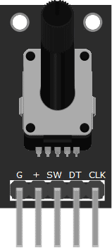
The KY-040 Module will be our main component for this tutorial. This module has an Incremental Rotary Encoder mounted on a breakout board. Figure 1 shows the module as seen in fritzing.
Pin Out
The KY-040 module has five pins.
| Pin | Description |
|---|---|
| G | Encoder Pin C (Common) |
| (+) | +5V |
| SW | Switch (N.O.) |
| DT | Encoder Pin B |
| CLK | Encoder Pin A |
What is a Rotary Encoder?
An Incremental Rotary Encoder is a position sensor used to determine how much the shaft is rotated and the direction of rotation. An encoder contains two switch mechanisms that change state depending on when the encoder shaft is turned. By analyzing the pulses produced by the switches, we can determine the direction of rotation and the amount of rotation.
Project - Arduino Rotation Indicator
After learning about the KY-040 module and the Incremental Rotary Encoder, it is now time to build a project using the module. Our project will get digital signals from the KY-040 module, and display it on the serial monitor.
Components
For this project, we need the following components:
- Arduino Uno board (1 pc.)
- KY-040 Rotary Encoder Module (1 pc.)
- Jumper wires
Wiring Diagram
Figure 2 shows the connection between the Arduino Uno and the KY-040 Rotary Encoder Module.
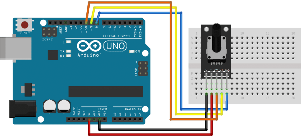
The KY-040 module pins are connected to the Arduino Uno board as follows:
| Component Pin | UNO Board Pin |
|---|---|
| G | GND |
| (+) | +5V |
| SW | 10 |
| DT | 9 |
| CLK | 8 |
Code
Below is the Arduino sketch for our project. I have added comments to explain important parts of the code. Save the code as KY-040.ino and upload it to your Arduino board.
					// Arduino and KY-040 module
int encoderPinA = 8; // CLK pin
int encoderPinB = 9; // DT pin
int encoderBtn = 10; // SW pin
int count = 0;
int encoderPinA_prev;
int encoderPinA_value;
boolean bool_CW;
void setup() {
Serial.begin (9600);
pinMode (encoderPinA, INPUT);
pinMode (encoderPinB, INPUT);
pinMode(encoderBtn, INPUT_PULLUP);
encoderPinA_prev = digitalRead(encoderPinA);
}
void loop() {
encoderPinA_value = digitalRead(encoderPinA);
if (encoderPinA_value != encoderPinA_prev) { // check if knob is rotating
// if pin A state changed before pin B, rotation is clockwise
if (digitalRead(encoderPinB) != encoderPinA_value) {
count ++;
bool_CW = true;
} else {
// if pin B state changed before pin A, rotation is counter-clockwise
bool_CW = false;
count--;
}
if (bool_CW) {
Serial.print("Clockwise | ");
} else {
Serial.print("Counter-Clockwise | ");
}
Serial.print(count);
Serial.print(" | ");
}
encoderPinA_prev = encoderPinA_value;
// check if button is pressed (pin SW)
if (digitalRead(encoderBtn) == LOW) Serial.println("Button Pressed");
else Serial.println("Button Released");
}
Project Test
Apply power to your Arduino Uno board and open the Serial Monitor in the Arduino IDE. Try to rotate the encoder shaft and observe the output in the Serial Monitor. Arduino will output the direction of rotation, shaft position, and state of the button (pressed/released) on the serial monitor.