Introduction
In this tutorial, we will learn about the KY-033 module, how it works and we will build a simple project using the KY-033 module and an Arduino.
Tracking Sensor Module KY-033
The KY-033 Module will be our main component for this tutorial. This module has IR transmitter/receiver, and an LM393 differential comparator mounted on a breakout board with a potentiometer and several resistors. Figure 1 shows the module as seen in fritzing.

Pin Out
The KY-033 module has three pins.
| Pin | Description |
|---|---|
| G | Ground |
| V+ | +5V |
| S | Signal |
How it Works
The KY-033 module detects if the surface in front of the IR transmitter/receiver absorbs or reflects light. A dark surface absorbs light while a light surface reflects light. If the surface is dark, the module Signal pin will be pulled HIGH. And if the surface is light, the signal pin will be LOW.
Project - Arduino Line Detector
After learning about the KY-033 module and how it works, it is now time to build a project using the module. Our project will get the digital signal from the KY-033 module, display a message on the serial monitor, and control the Arduino’s built-in LED.
Components
For this project, we need the following components:
- Arduino Uno board (1 pc.)
- KY-033 Tracking Sensor Module (1 pc.)
- Jumper wires
Wiring Diagram
Figure 2 shows the connection between the Arduino Uno and the KY-033 Tracking Sensor Module.
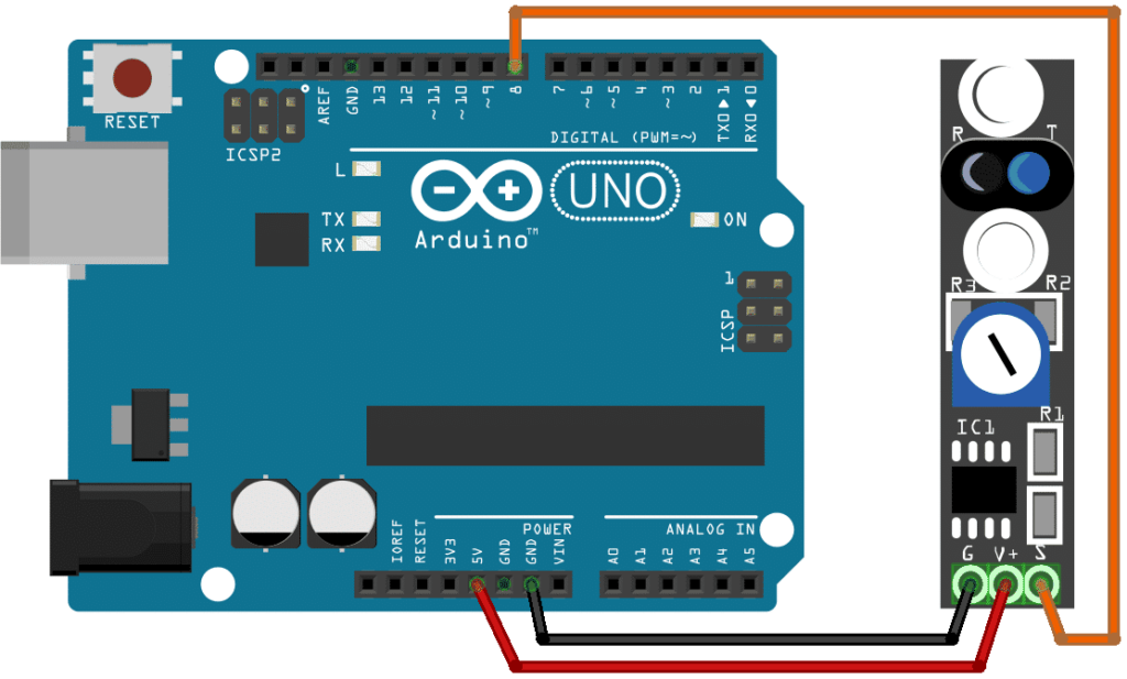
The KY-033 module pins are connected to the Arduino Uno board as follows:
| Component Pin | UNO Board Pin |
|---|---|
| G | GND |
| V+ | +5V |
| S | 8 |
Code
Below is the Arduino sketch for our project. I have added comments to explain important parts of the code. Save the code as KY-033.ino and upload it to your Arduino board.
					// Arduino and KY-033 module
void setup ()
{
pinMode (13, OUTPUT); // built-in LED pin set to output
pinMode (8, INPUT); // module signal output connected to Arduino pin 8
Serial.begin(9600); // initialize serial
}
void loop ()
{
if (digitalRead(8) == HIGH) { // if module detects a dark surface,
Serial.println("Dark Surface"); // show message on serial monitor and
digitalWrite (13, HIGH); // switch-On built-in LED
}
else {
Serial.println("Light Surface");
digitalWrite (13, LOW);
}
}
Project Test
Apply power to your Arduino Uno board and open the Serial Monitor in the Arduino IDE. Arduino will output “Dark Surface” on the serial monitor and switch-on the Arduino’s built-in LED if it detects a dark surface. The message “Light Surface” and the LED will be off if it detects a light surface. The sensitivity of the module can be adjusted via VR1.