An Arduino UNO basically has these components to function well with the Arduino IDE.
ATMEGA328P MCU
16 MHz Crystal oscillator
2 pcs. 22pF NPO ceramic capacitor for matching with the crystal
A 5V voltage regulator (7805 or AMS117-5)
A 3.3V voltage regulator (optional)
LEDs for
Power
D13 (Builtin LED)
Programming activity (SCK or TX/RX pins)
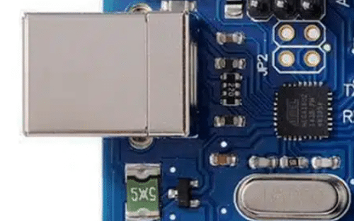
USB-to-Serial converter board (CH340, FTDI, etc.) for bootloader mode programming
Buffer transistor for signal LEDs
Filter capacitors
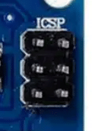
6-pin AVR ISP header for direct/ISP programming
CONSTRUCTION on a Breadboard
It is possible to create your Arduino UNO on only a breadboard. This is a great way to start learning the parts and processes of this indispensable development board. Below is a summary of the different circuits involved.
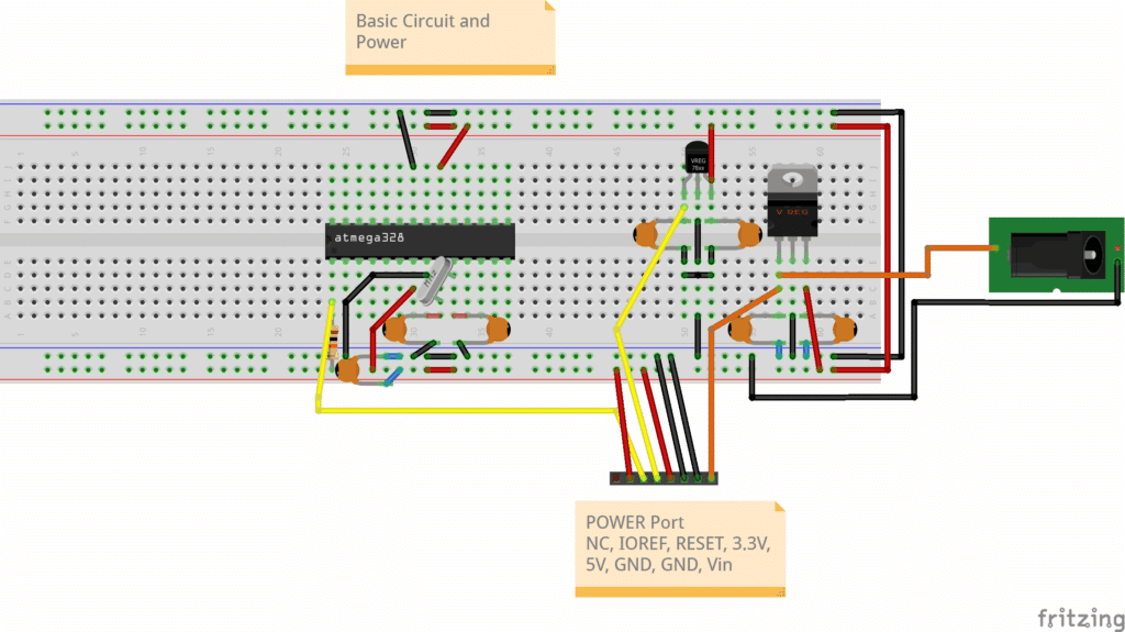
Basic Circuit with Power Supply
Below is a circuit to power and run an Arduino UNO with 5V along with an optional 3.3V supply. You may use the 7805 and 78L33 voltage regulators for this. The DC jack should be supplied with a voltage 2V – 3V higher than 5V. Note that a 16 MHz crystal oscillator is attached along with some matching caps. The reset line is pulled up to Vcc via a 10K resistor. Note that the connections of the power and GND pins of the ATMEGA328P include the AVcc pin.
Connection
ATMEGA328P
Comment
Vcc
pin 7
Digital Supply (5V)
AVcc
pin 20
Analog Supply (5V)
GND
pin 8
Ground
GND
pin 22
Ground
XTAL1
pin 9
via 22pF cap to GND
XTAL2
pin 10
via 22pF cap to GND
RESET PIN
pin 1
pull up 10K Resistor
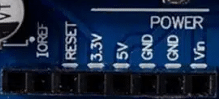
The power port should match what an original Arduino UNO has. It has IOREF, RESET, 3.3V, 5V, GND (2X), and Vin. IOREF is used to match I/O voltage from board to board, where it is basically just 5V using the UNO and shields for it. The first port is reserved (NC).
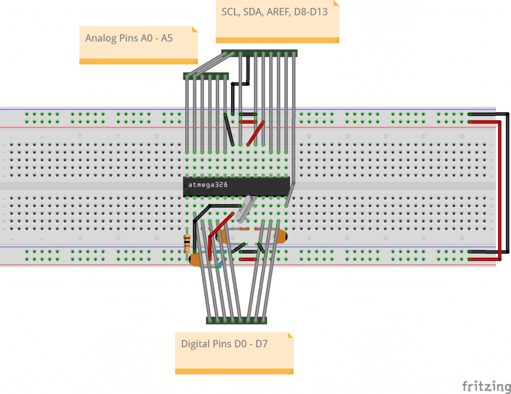
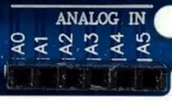
The Ports (Analog and Digital)
Next, here is a separate view of the circuit connections of the Analog and Digital ports of the UNO. Basically, all the analog and digital lines are output, as well as I2C lines (which are also analog ports A4 and A5). The AREF port determines the ADC reference voltage.
Port Function
ATMEGA328P Pin
Comment
A0
pin 23
Analog
A1
pin 24
Analog
A2
pin 25
Analog
A3
pin 26
Analog
A4
pin 27
Analog/I2C - SCL
A5
pin 28
Analog/I2C - SDA
D0
pin 2
Digital
D1
pin 3
Digital
D2
pin 4
Digital
D3
pin 5
Digital/PWM
D4
pin 6
Digital
D5
pin 11
Digital/PWM
D6
pin 12
Digital/PWM
D7
pin 13
Digital
D8
pin 14
Digital
D9
pin 15
Digital/PWM
D10
pin 16
Digital/PWM
D11
pin 17
Digital/PWM
D12
pin 18
Digital
D13
pin 19
Digital
AREF
pin 21
ADC Referrence Voltage
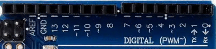
On an UNO you’ll see the ports as:
Programming POrts
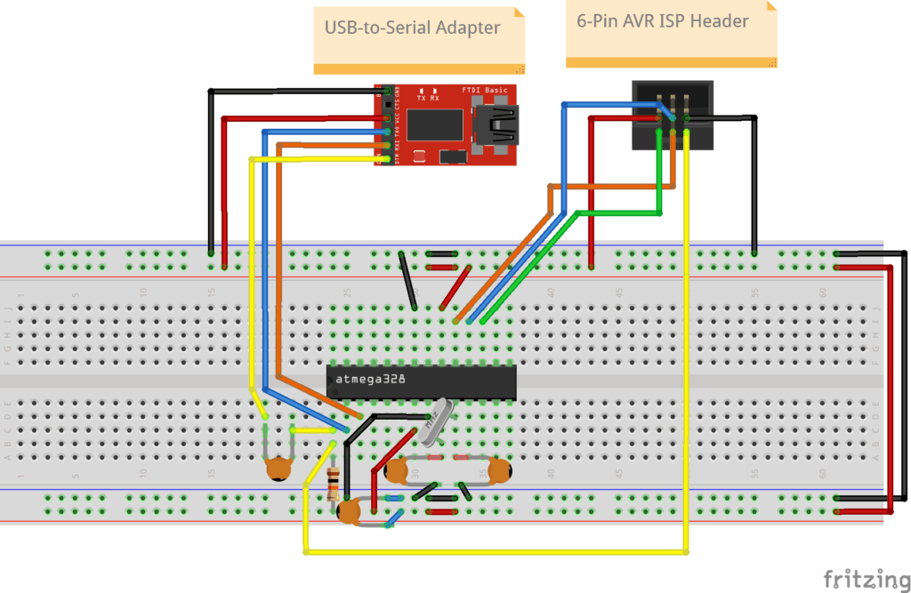
On an UNO, you’ll see both a USB port (with a dedicated USB-to-Serial chip such as ATMEGA16u2, or CH340) and an ICSP port. These ports are used for programming the main ATMEGA328P chip. The USB-to-Serial chip is used for Bootloader, while the ICSP port is for In-Circuit Serial Programming mode. Learn more about the programming modes of the ATMEGA328P here. It’s best to have both modes available on your UNO circuit.
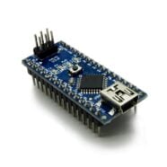
USB-to-Serial Adapter
ATmega328P
VCC (5V)
VCC (Pin 7)
GND
GND (Pin 8)
AVCC (pin 20)
GND (pin 22)
TXD
RXD (Pin 2)
RXD
TXD (Pin 3)
DTR
RESET (Pin 1) via a 0.1µF capacitor and RESET (Pin 1) pulled up to Vcc via 10k resistor.
OSC1 (Pin 9) via XTAL and NPO Cap to GND
OSC2 (Pin 10) via XTAL and NPO Cap to GND
6-pin ISP Programmer
ATmega328P
VCC
VCC (Pin 7)
GND
GND (Pin 8)
MOSI
MOSI (Pin 17)
MISO
MISO (Pin 18)
SCK
SCK (Pin 19)
RESET
RESET (Pin 1) - pull up to VCC via 10K resistor
AVCC (Pin 20)
GND (Pin 22)
OSC1 (Pin 9) via XTAL and NPO Cap to GND
OSC2 (Pin 10) via XTAL and NPO Cap to GND
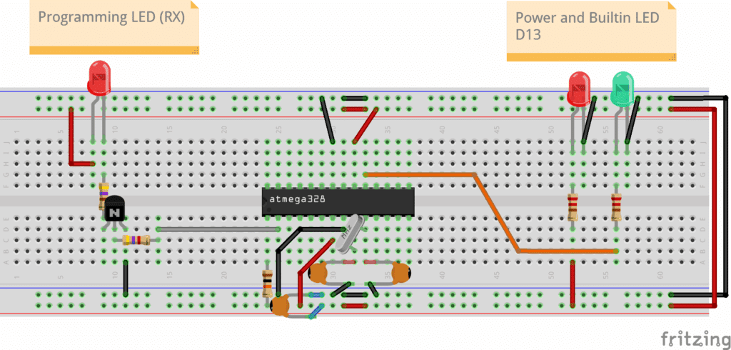
Signal LEDs
The signal LEDs provide visual information to the user about certain functions in the circuit. Information such as power, built-in LED, and programming activity. Sometimes, you’ll need a buffer (such as a transistor) to not disrupt the actual function of the port (such as during UART transmission).
Function
ATMEGA328P Pin
Comment
Power
Vcc
5V Power Indicator
Built-in LED
pin 19
LED Port
Programming Indicator
pin 2
UART RX port (Bootloader mode programming)
Conclusion
You just learned about the different circuits and connections involved in an Arduino UNO development board. With this, you should be able to construct your own UNO. Why not try to layout this circuit on a printed circuit board?