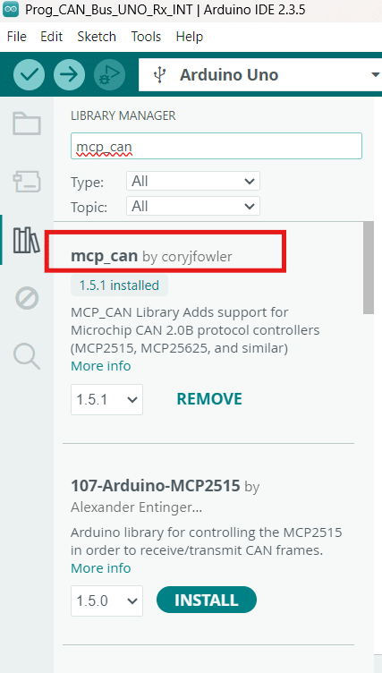
Want to go hands-on on CAN bus? Go ahead and browse through this CAN bus programming guide.
Introduction
You had an Introduction to CAN Bus on the previous blog. Now, you’re going to learn actual CAN bus programming on your Arduino. It’s easy to do this since there’s already a built-in library for using CAN.
CAN Bus Circuit
What You'll Need:
The main component needed is the MCP2515 CAN bus module. This module has both a CAN bus transceiver and controller. The transceiver is an A1050 while the controller an MCP2515 chip. Below is the list of things you’ll need:
- 2x or more MCP2515 CAN Bus Module
- Arduino UNO, Nano, MEGA, or others types (with USB cables)
- 2 Colored wires for the CAN Bus and nodes
- Optional screw terminal connectors
- 2x 120 ohms resistors (termination resistor) or jumper terminals (for the MCP2515 module)
- Connecting wires
MCP2515 CAN Bus Module
Circuit Setup
Basically, you’ll want to wire up your Arduinos to the CAN Bus modules through the SPI lines, power lines, and even the INT line (Interrupt line). As for the CAN bus, you can simulate the bus through 2 straight stranded wires. Connect the MCP2515 modules as nodes to these CAN bus lines. The optional blue screw connectors are there just to prevent the CAN bus from shorting out. You can also optionally place termination resistors at the end of these terminals. However, as you’ll see here, the MCP2515 modules themselves have these termination resistors built in. You can enable them by shorting the corresponding jumper (J1) on only both ends of the CAN bus line.
Connections:
| MCP2515 Pin | Arduino UNO/NANO Pin | Description |
|---|---|---|
| VCC | 5V | Power supply |
| GND | GND | Ground |
| CS | D10 | SPI Chip Select |
| SO | D12 | SPI MISO (Master In Slave Out) |
| SI | D11 | SPI MOSI (Master Out Slave In) |
| SCK | D13 | SPI Clock |
| INT | D2 | Interrupt pin (optional but useful) |
| MCP2515 Pin | Arduino MEGA Pin | Description |
|---|---|---|
| VCC | 5V | Power supply |
| GND | GND | Ground |
| CS | D53 | SPI Chip Select |
| SO | D50 | SPI MISO (Master In Slave Out) |
| SI | D51 | SPI MOSI (Master Out Slave In) |
| SCK | D52 | SPI Clock |
| INT | D2 | Interrupt pin (optional but useful) |
Programming
Open an Arduino IDE sketch and then go to Library Manager. Add the MCP_CAN library by Cory Fowler.
Transmitter Code
Below is an example of a CAN bus transmitter code:
#include
#include
const int SPI_CS_PIN = 10;
MCP_CAN CAN(SPI_CS_PIN);
void setup() {
Serial.begin(115200);
while (CAN_OK != CAN.begin(MCP_ANY, CAN_500KBPS, MCP_8MHZ)) {
Serial.println("CAN init failed");
delay(100);
}
CAN.setMode(MCP_NORMAL);
Serial.println("CAN init OK!");
}
void loop() {
byte data[] = {0x01, 0x02, 0x03, 0x04, 0x01, 0x02, 0x03, 0x04}; // Example payload
CAN.sendMsgBuf(0x100, 0, 8, data); // ID: 0x100, Standard frame, 8 bytes
Serial.println("Message sent");
delay(1000);
}
Create an instance of the MCP_CAN class (CAN) with the SPI chip select pin parameter. Initialize the CAN bus with CAN.begin() with the parameters MCP_ANY (Accept all Messages), CAN_500KBPS (CAN clock speed), and MCP_8MHz (Crystal of the MCP2515 module).
Additionally, set the mode as CAN.setMode(MCP_Normal). This ensures the MCP2515 is not in LoopBack, Listening mode, or other types of modes.
Receiver Code
Below is the code for the receiver. Note that this code uses the INT pin to make receiving more efficient by using this hardware function.
#include
#include
#define CAN_CS_PIN 10
#define CAN_INT_PIN 2
MCP_CAN CAN(CAN_CS_PIN);
volatile bool canInterruptFlag = false;
void setup() {
Serial.begin(115200);
// Initialize CAN at 500 kbps with 8 MHz crystal
if (CAN.begin(MCP_ANY, CAN_500KBPS, MCP_8MHZ) == CAN_OK)
Serial.println("CAN Initialized");
else
Serial.println("CAN Init Failed");
CAN.setMode(MCP_NORMAL); // Normal receive mode
// Attach interrupt on falling edge
attachInterrupt(digitalPinToInterrupt(CAN_INT_PIN), onCANReceive, FALLING);
}
void loop() {
if (canInterruptFlag) {
canInterruptFlag = false;
//Serial.println("INT happened");
long unsigned int rxId = 0x100;
unsigned char len = 0;
unsigned char rxBuf[8];
while (CAN.checkReceive() == CAN_MSGAVAIL) {
byte len = 0;
byte buf[8];
CAN.readMsgBuf(&rxId, &len, rxBuf);
Serial.print("Received: ");
for (byte i = 0; i < len; i++) {
Serial.print(rxBuf[i], HEX);
Serial.print(" ");
}
Serial.println();
}
}
}
void onCANReceive() {
canInterruptFlag = true;
}
The atttachInterrupt() statement attaches the CAN INT pin to the onCANReceive ISR and uses the FALLING edge of the signal since the INT pin becomes active at a low level.
In the loop, the canInteruptFlag is polled. When true, CAN.checkReceive() checks for message availability. This statement also ensures you have read all the CAN messages. CAN.readMsgBuf() receives the message with ID rxID (0x100) through a for loop (with len as length and rxBuf as array). The values are printed on the serial monitor.
Actual RUN
SHOP THIS PROJECT
-
MCP2515 Can Bus Module TJA1050 Receiver Board
$19.95Original price was: $19.95.$16.95Current price is: $16.95. Read more