Create a useful DIY ATtiny85 timer for your everyday needs using the WOKWI Arduino Simulator.
(Timer upgrade with time selection through OLED display will be up on the next series)
Introduction
Several activities or chores require precise timing. For example, you may want to boil an egg just right so that it is soft and edible. This process takes approximately 3 minutes. However, it’s hard to keep count, and you don’t want to always mess up with your smartphone settings. Another example is a work time sitting timer. Studies show that long hours sitting all day can lead to various health consequences. Making a handy DIY timer for these needs would be a great idea.
Create A Simple ATtiny85 based timer
Here is an ATtiny85 based timer hardware on a breadboard that will be simulated on the WOKWI Arduino simulator
Components you'll need
You’ll just need several off-the-shelf electronic components for your handy timer. This includes the classic ATtiny85 MCU.
- ATtiny85-20P or 10P microcontroller
- 1pc. 1k 1/4 resisitor
- 0.1uF Ceramic Disc Capacitor (for filter, omitted on some images, but required)
- 1pcs. Tact Switch (normally open)
- 3V Active Tone Buzzer
- 2AA Battery Holder
- A breadboard to simulate your circuit
- Some connecting wires
You’ll also need an ISP Programmer to program your ATtiny85. This can be an Arduino module (such as UNO or mini) or better yet, have your own stand-alone AVR ISP Programmer.
Circuit Layout
The circuit layout in Fritzing is below:
Start to COde
Optionally use an easy-to-use Circuit Simulator
Previously, a popular online electronic circuit simulator was introduced in The WOKWI Online Electronics Simulator. You may want to check this out. This tool can greatly help especially if you do not have the components yet on hand, or you are always working on the go away from your workbench. Having a simulator can also simplify or fast-track the development of your electronic projects. Otherwise, if you’re the hands-on type, gather the components to test them out on a breadboard while debugging this project on the Arduino IDE.
Start WOKWI and ADD your Components
Below is a demo of starting WOKWI from your browser and choosing the ATtiny85 MCU. This project begins as a Blinky project and continues from there. Go to Docs and scroll through Supported Hardware -> choose ATtiny85. Then scroll through Simulator Examples -> choose ATtiny85 Blink.
Rename this project (please save it too! (not shown on the video)). Next, you can add the necessary components to your timer by clicking the + icon. A buzzer, a push button switch, and a resistor are added to the project.
(Note that a push button with pull-up resistor was used here. You can use the pull-up capability of an ATtiny85 port next time)
Coding for the Timer
To make a reliable timer for the ATtiny85, you can use the millis() function. The millis() function returns the number of milliseconds that passed since the start of your code (only resetting after 50 days!). Below is code that alarms (using a buzzer) after a defined period after starting the timer with a push button.
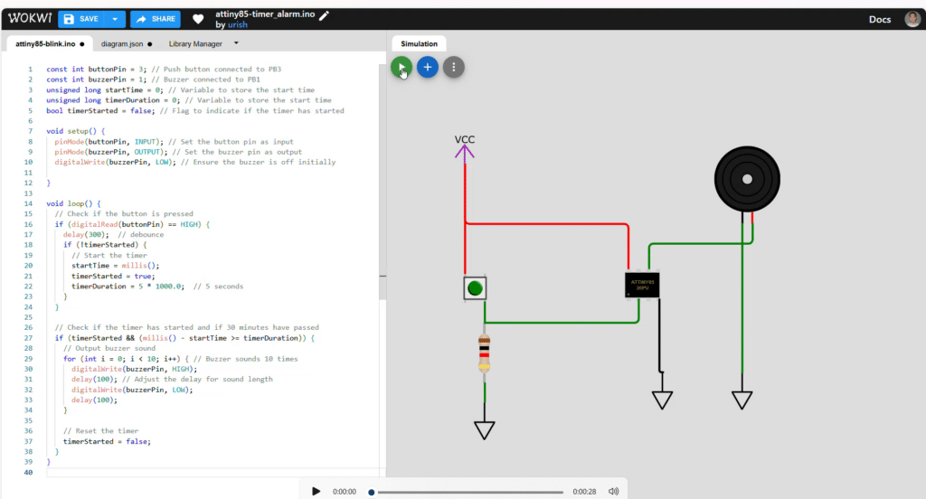
const int buttonPin = 3; // Push button connected to PB3
const int buzzerPin = 1; // Buzzer connected to PB1
unsigned long startTime = 0; // Variable to store the start time
unsigned long timerDuration = 0; // Variable to store the start time
bool timerStarted = false; // Flag to indicate if the timer has started
void setup() {
pinMode(buttonPin, INPUT); // Set the button pin as input
pinMode(buzzerPin, OUTPUT); // Set the buzzer pin as output
digitalWrite(buzzerPin, LOW); // Ensure the buzzer is off initially
}
void loop() {
// Check if the button is pressed
if (digitalRead(buttonPin) == HIGH) {
delay(300); // debounce
if (!timerStarted) {
// Start the timer
startTime = millis();
timerStarted = true;
timerDuration = 5 * 1000.0; // 5 seconds
}
}
// Check if the timer has started and if the timerDuration time have passed
if (timerStarted && (millis() - startTime >= timerDuration)) {
// Output buzzer sound
for (int i = 0; i < 10; i++) { // Buzzer sounds 10 times
digitalWrite(buzzerPin, HIGH);
delay(100); // Adjust the delay for sound length
digitalWrite(buzzerPin, LOW);
delay(100);
}
// Reset the timer
timerStarted = false;
}
}
You can add this code on the left part of the WOKWI coding window.
Simulating the Timer in WOKWI
The code and circuit can be simulated in WOKWI simply by pressing the play button. After pressing play, you can interact with the circuit by pressing the push button. Wait for 5 seconds, and you should see your buzzer animate with sounds. After this, please remember to save your project.
Testing your Timer in Hardware
Of course, the simulation is useless unless you implement it in hardware. To test it on hardware, you must first download your WOKWI simulation code on your PC. Note that in case you have issues with the folder structure of your saved file in Arduino, simply choose OK so Arduino can correct it.
HOw to Program your ATtiny85
Previously, you’ve learned How to Program an ATtiny85 using Arduino. You can apply that concept here to be able to program this project. Additionally, you can also program your ATtiny85 using a stand-alone AVR ISP Programmer to avoid confusing connections. Below is an example run of programming your ATtiny85 using a USBTinyISP programmer. Choose similar settings and remember to burn the bootloader first before uploading code using the ISP programmer.
After programming, you can run the circuit running on the bread board. Pressing the tact switch starts the duration timer. The alarm goes on when the desired time is reached. You can press the timer again to restart the timer all over again.
Hope you have learned a lot in this ATtiny85 timer WOKWI Arduino walkthrough.
This timer would be more interactive if an OLED module is installed. You can add more options to this timer through the OLED user interface. This will be a good topic for the next blog.