Phipps Electronics

Order within the next 

FREE SHIPPING OVER $199

50,000+ ORDERS

WORLDWIDE SHIPPING

SSL SECURED

Introduction to 7-Segment Displays with Arduino

Contents

Getting a seven-segment display to work with Arduino takes only a few minutes to learn. Learn how to get these displays going quickly.

What's Inside a 7-Segment display?

Inside a 7-segment display are a couple of LEDs lighting each display segment. A 7-segment display has two configurations, namely, common-anode and common-cathode. In a common anode, all the anodes of the LEDs are tied together, while for a common cathode, the cathodes are the ones tied up.

Below is a simple circuit setup of a common anode 7-segment LCD that you can test:

The common ground and 5 V pins are required for its power source. The other pins act as switches for the internal LEDs within each segment. Resistors are connected with each LED to limit the current draw of each LED.

7 Segment Display Pinout

COM is the common pin. If you have a common anode seven-segment LCD, you’ll usually connect this to the positive voltage supply. The pins with the letters a to h are driven with resistors by the digital output pins of the Arduino. A low value will light up the segment, while a high value will turn it off.

If you have a common cathode LCD segment, then it will be the opposite. The common pin will usually be connected to the ground. The pins with the letters a to h are driven with resistors by the digital output pins of the Arduino. A high value will light up the segment, while a low value will turn it off.

Schematic Diagram

Here is a circuit setup that uses a common cathode LCD segment.

The Code

Below is a code snippet that counts backward from 9 to 0 for the circuit above.

				
					// make an array to save Sev Seg pin configuration of numbers

int num_array[10][7] = {  { 1,1,1,1,1,1,0 },    // 0
                          { 0,1,1,0,0,0,0 },    // 1
                          { 1,1,0,1,1,0,1 },    // 2
                          { 1,1,1,1,0,0,1 },    // 3
                          { 0,1,1,0,0,1,1 },    // 4
                          { 1,0,1,1,0,1,1 },    // 5
                          { 1,0,1,1,1,1,1 },    // 6
                          { 1,1,1,0,0,0,0 },    // 7
                          { 1,1,1,1,1,1,1 },    // 8
                          { 1,1,1,0,0,1,1 }};   // 9

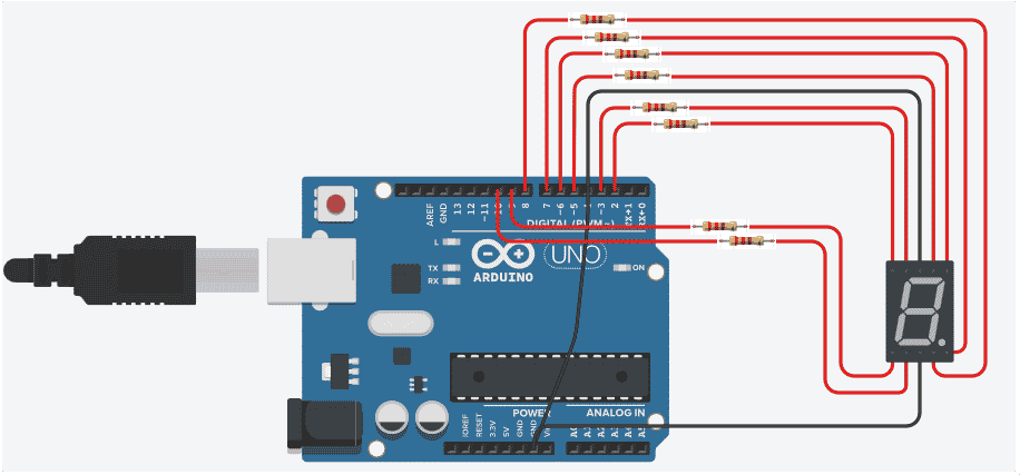
int pin_array[7] = {5, 6, 8, 9, 10, 3, 2 };
                                       
//function header
void Num_Write(int);

void setup() 
{ 
  // set pin modes
  pinMode(2, OUTPUT);  //G
  pinMode(3, OUTPUT);  //F
  pinMode(5, OUTPUT);  //A
  pinMode(6, OUTPUT);  //B
  pinMode(8, OUTPUT);  //C 
  pinMode(9, OUTPUT);  //D
  pinMode(10, OUTPUT); //E
}

void loop() {
  
  //counter loop
  
  for (int counter = 10; counter > 0; --counter) 
  {
   delay(500);
   Num_Write(counter-1); 
  }
  delay(1000);
}

// this functions writes values to the 7 segment pins  
void Num_Write(int number) 
{
  for (int j=0; j < 7; j++) {
   digitalWrite(pin_array[j], num_array[number][j]);
  }
}


Conclusion

The two kinds of 7-segment display configurations were discussed. A simple circuit was used together with an Arduino code, demonstrating the ability to count backwards from 9 to 0.

SUBSCRIBE FOR NEW POST ALERTS

Subscribe to be the first to know when we publish a new article!
List Subscriptions(Required)

POPULAR POSTS

Scroll to Top