Have you heard about multivibrator circuits? Do you know where you can apply these? See the rest of the article to find out.
Introduction
Multivibrator circuits are an excellent way to learn basic electronics. These circuits are usually taught in every electronics curriculum. If you look closely, they can be composed of simple discrete components such as transistors, resistors, capacitors, and an IC to name a few. If you have prior knowledge of these components and can connect them as a circuit, you’ll be able to create a basic multivibrator in no time.
What is a Multivibrator Circuit?
A multivibrator is defined as a circuit that switches between two (transient) states. It depends on its circuit configuration on how it implements these states. The two states can be used to generate practical waveforms that you can use in your everyday circuits.
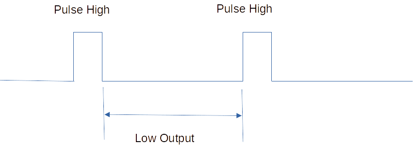
As an example, consider 2 series of outputs from a multivibrator circuit containing a pulse high and low output.
These outputs were generated from a circuit with 2 states (an example of this will follow) that may or may not be triggered externally. You can use the pulse high output to trigger an event while the low output serves as a rest period before another pulse high trigger output occurs.
Another example of a multivibrator output is a continuous sawtooth or a square wave that you’ll surely find useful in your circuits. This output is generated by an Astable Multivibrator (that you’ll learn later) that has two continuously changing states.
Different Kinds of Multivibrator Circuits
Astable Multivibrator
An Astable Multivibrator works with two states continuously. No states are stable because it continuously switches from one state to the other. Because of this, a continuous waveform can be made. A square wave or a sawtooth wave is an example of this waveform. Additionally, Astable Multivibrators don’t need any external trigger for them to work. It continuously outputs its waveform as long as the two states change. The state changes can alternatively internally trigger themselves to produce the waveform.
Astable Multivibrator Circuit Example - 555 Timer in Astable Mode
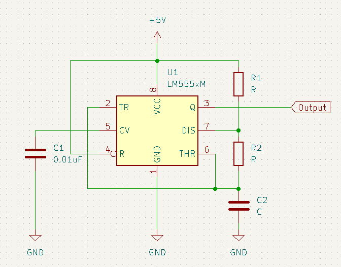
Here is a simple triggerless astable multivibrator circuit using the popular 555 timer IC. R1 and R2 serve as current paths to charge and discharge the capacitor C2 through the TR, THR, and DIS pins. The value of these components determines the pulse width and frequency of the waveform. C1 is only used for noise suppression. In Astable mode, the 555 timer’s Trigger and Threshold pins are shorted together. The output can be seen at pin 3.
Pulse high duration is determined by the equation:
0.693(R1 + R2) C2
While for the low duration:
0.693 R2 C2
Monostable Multivibrator
Also called “One-Shot”, these multivibrators are externally triggered to transition from one state and then return back to their original state. As an example, a circuit that outputs a low signal can be woken up by an external signal to output a high signal for a known duration. After this, it goes back to being low again. A Monostable Multivibrator can be found on many digital circuits that need a digital pulse as input to create an event.
Monostable Multivibrator Circuit Example - 555 Timer in "One-Shot" Monostable Mode
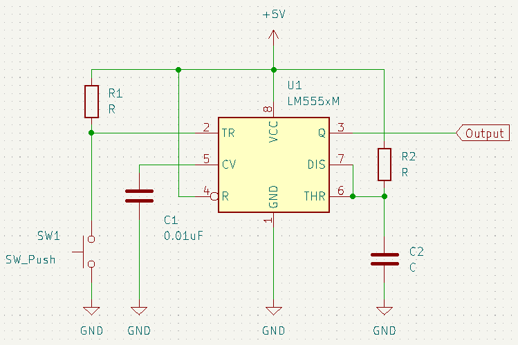
This 555 “One Shot” Multivibrator has 1 trigger input implemented as a normally open switch in series with R1 to Vcc. The switch is connected to the TR input. The Discharge (DIS) and Threshold (THR) pins are shorted together and connect directly to R2 and C2. These components determine the length of the momentary triggered pulse.
The formula for the length of the pulse is given as:
1.1 R2 C2
Bistable Multivibrator
If an Astable Multivibrator has two changing states, a Bistable Multivibrator has two stable states. These states can be triggered to go back and forth with one another. Think of it in terms of Flip flop circuits. An RS flip-flop (also called a Set-Reset flip-flop) does exactly what a Bistable Multivibrator can do. Triggering the Set input of the flip-flop will output a high while triggering the Reset input will output a low on the output.
Bistable Multivibrator Circuit Example - 555 Timer in Bistable Mode
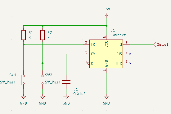
The 555 timer in Bistable multivibrator mode can be triggered with 2 switches to switch states and output either a high or low on a single output pin. One switch is connected to the TR (trigger) pin while the other is connected to the R (reset) pin. Internally, the 555 timer has an RS flip-flop which serves as a single-bit memory element to remember the states.
A Bistable MV works in that when there is a momentary trigger on the TR pin, the Q outputs a High and stays there. When a momentary trigger on the R pin occurs, Q outputs a Low and stays there.