This article will help you build a current source out of your transistor along with a few extra components.
Introduction
Transistors are handy little components that you can use in your everyday electronics needs. You can use it as an electronic switch, or an amplifier. Pair it up with other semiconductors and you can create a simple voltage regulator or current source. In this article, you’ll learn how to create some practical current sources out of the shelf components on your workbench.
Before anything else, you may want to browse this relevant blog:
Transistor with Zener Diode as a Constant Current Source
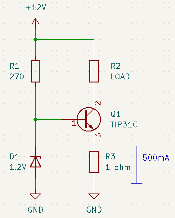
Here is a transistor used as a simple current source using only a Zener diode as a voltage reference. If you look closely, the current across the load should equal the emitter current which is about 500mA. You can get the emitter current through the KVL equation:
1.2V = 0.7V + R3 * IR3
IR3 = 1.2V – 0.7V / R3
IR3 = ILOAD = 500mA
Supply the Zener diode with enough current to maintain its Iz (Zener current) without being disturbed by any light loads. You can approximately set your Zener current to be 10% of its maximum current capacity based on your Zener’s power capacity.
Transistor with Op-AMP as Constant Current Source

Here FET is used along with an OP-Amp to produce constant current. The OP-Amp is a better, yet more expensive approach due to its wider characteristic range. The OP-Amp will try to vary the gate voltage of the FET until it reaches the desired voltage across the sense resistor R5. With the desired voltage, you can get the intended current through Ohm’s law. This voltage can be set through the voltage divider network resistor R2 and R4 which is fed to the non-inverting input of the OP-Amp. Confluently, the OP-Amp will now try to make the non-inverting input voltage value equal to its inverting input. You can use a potentiometer in place of the voltage divider to vary the actual current.
Transistor with Op-AMP as High Side Constant Current Source Approach
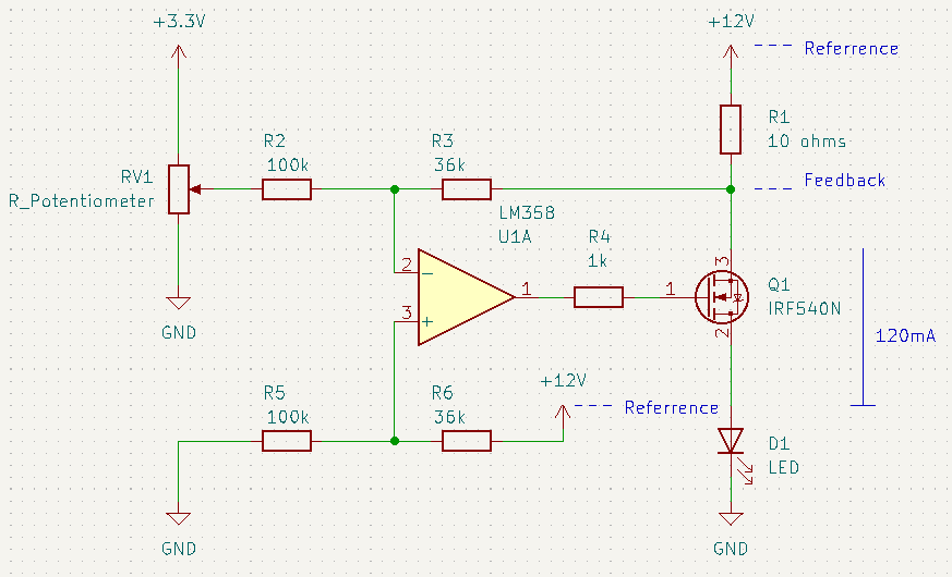
Some people like to have a current source that supplies power to a grounded load. With this, you need a high-side current source. The high-side current source will have a sense resistor that samples near +Vcc rather than ground.
Consider the circuit above. The circuit is a difference amplifier OP-AMP circuit.
To simplify things, we can set
- R2 = R5 and R3 = R6.
With some of the resistor values equal, you’ll have a voltage gain equal to the simplified equation for a differential op-amp of R3/R2.
- Vo = Vi (R3/R2)
The sense resistor is R1. We need to know the potential across this to be able to determine the constant current. This is where we get feedback. At the same time, our reference is Vcc and not ground.
The plan is to have a maximum load current of 120mA. With 10 ohms as a sense resistor, we should have a swing of 0 – 1.20V on the output.
For the input (potentiometer), the plan is to have 0 – 3.3V.
From equation (2) we have:
1.2V = 3.3V(R3/R2)
So the gain would be R3/R2 = 1.2V/3.3V = 0.3636
We can set R3 = 36k since R2 is set at 100k.
R6 would be 36k.
You may need to adjust these values though for real-world scenarios.


