Phipps Electronics

Order within the next 

FREE SHIPPING OVER $199

50,000+ ORDERS

WORLDWIDE SHIPPING

SSL SECURED

Using the 2 Colour LED Module KY-011 with Arduino

Contents

Introduction

In this tutorial, we will learn about the KY-011 module, what is a 2-color LED and we will build a simple 2-color blinker using an Arduino and the KY-011 module.

2 Colour LED Module KY-011

The KY-011 Module will be our main component for this tutorial. This module has a 2-color LED mounted on a breakout board. Figure 1 shows the module as seen in fritzing.

Figure 1: KY-011 2 Colour LED Module

Pinout

The KY-011 module has three pins.

Component PinArduino Uno board Pin
(-)Green
middleRed
SGND

What is a 2 Colour LED?

A 2-color LED is simply two different colored LED’s assembled in one package. The color of each LED is Red, and Green.

Project - Arduino 2 Colour Blinker

After learning about the KY-011 module and the 2-colour LED, it is now time to build a project using the module. Our project will alternate the color (red/green) of the LED every one-second.

Components

For this project, we need the following components:

  • Arduino Uno board (1 pc.)
  • KY-011 2 Colour LED Module (1 pc.)
  • 220-ohm resistor (2 pcs.)
  • Breadboard (1 pc.)
  • Jumper wires

Wiring Diagram

Figure 2: Connection Diagram

Figure 2 shows the connection between the Arduino Uno and the KY-011 2 Colour LED Module. The two 220-ohm resistors are needed between the Arduino and the Green and Red pins of the KY-011 to protect the LED from over-current.

The KY-011 module pins are connected to the Arduino Uno board as follows:

Component PinResistorArduino Uno board Pin
(-)220 Ohms9
middle220 Ohms8
S-GND

The Code

Below is the Arduino sketch for our project. I have added comments to explain important parts of the code. Save the code as KY-011.ino and upload it to your Arduino board.

				
					// Arduino and KY-011 module
void setup() {
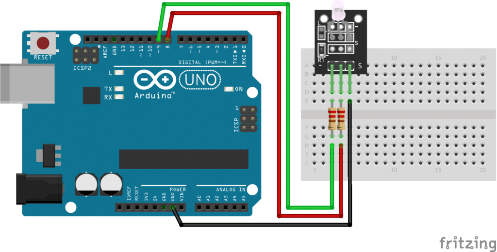
  pinMode(8, OUTPUT); // module's red pin
  pinMode(9, OUTPUT); // module's green pin
  digitalWrite(8, LOW); // switch off red
  digitalWrite(9, LOW);
}
void loop() {
  digitalWrite(8, HIGH);  // switch on red
  delay(1000);            // wait 1 second
  digitalWrite(8, LOW);   // switch off red
  digitalWrite(9, HIGH);  // switch on green
  delay(1000);            // wait 1 second
  digitalWrite(9, LOW);   // switch off green
}


Project Test

Apply power to your Arduino Uno board. The KY-011 should alternate color every one-second.

SUBSCRIBE FOR NEW POST ALERTS

Subscribe to be the first to know when we publish a new article!
List Subscriptions(Required)

POPULAR POSTS

Scroll to Top