Introduction
This tutorial details the 433MHZ RF Wireless Transmitter and Receiver Module Kit, its functions and the process to build a project using the 433MHZ RF Wireless Transmitter and Receiver Module Kit and an Arduino.
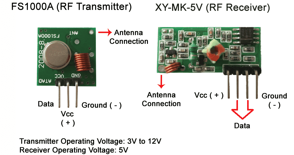
The 433MHz RF Wireless Transmitter & Receiver Kit
The 433Mhz RF transmitter with receiver module kit consists of an XD-RF-5V 433MHz receiver and XD-FST 433MHz transmitter. The kit can create a wireless RF connection for a remote control switch, receiver module, or similar wireless applications/projects.

Pin Out
Transmitter
| Pin | Description |
|---|---|
| GND | Ground |
| VCC | Module Power Supply (3-12VDC) |
| ATAD | Data Output |
Receiver
| Pin | Description |
|---|---|
| VCC | Module Power Supply (5VDC) |
| D1 | Data Output1 |
| D2 | Data Output2 |
| GND | Ground |
How it Works
The 433Mhz RF transmitter with receiver module kit is composed of a transmitter and a receiver module. The kit creates a one-way wireless communication with 2 microcontrollers.
Project - Arduino Serial Data Sender & Reveiver
This project utilizes 2 sets of Arduino and 433Mhz RF transmitter with receiver module kits and demonstrates how a message is sent from one Arduino to the other.
Components
- Arduino Uno Board (2 pcs.)
- 433Mhz RF transmitter with receiver module kit (1 pc.)
- Jumper Wires
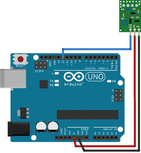
Wiring Diagram
Transmitter
| Pin | Arduino |
|---|---|
| GND | GND |
| VCC | 5V |
| ATAD | 12 |
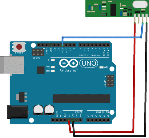
Receiver
| Pin | Arduino |
|---|---|
| VCC | 5V |
| D1 | No Connection |
| D2 | 11 |
| GND | GND |
Code
Download the library for the module first before proceeding. The library is available here; 433Mhz RF transmitter with receiver module library
Once the library is installed, the program code can be uploaded.
					TRANSMITTER:
#include <RH_ASK.h>
#include <SPI.h> // Not actually used but needed to compile
RH_ASK driver;
void setup()
{
    Serial.begin(9600);      // Debugging only
    if (!driver.init())
         Serial.println("init failed");
}
void loop()
{
    const char *msg = "MESSAGE FROM ARDUINO TRANSMITTER!";
    driver.send((uint8_t *)msg, strlen(msg));
    driver.waitPacketSent();
    delay(1000);
}
RECEIVER:
#include <RH_ASK.h>
#include <SPI.h> // Not actualy used but needed to compile
RH_ASK driver;
void setup()
{
    Serial.begin(9600);    // Debugging only
    if (!driver.init())
         Serial.println("init failed");
}
void loop()
{
    uint8_t buf[12];
    uint8_t buflen = sizeof(buf);
    if (driver.recv(buf, &buflen)) // Non-blocking
    {
      int i;
      // Message with a good checksum received, dump it.
      Serial.print("Message: ");
      Serial.println((char*)buf);
    }
}
Project Test
Once the components are wired as per the wiring diagram, connect the Arduino to the PC and upload the program. Open the Serial Monitor in the Arduino IDE on the receiver side and the following text will be displayed; “MESSAGE FROM ARUDINO TRANSMITTER”.


