Introduction
This tutorial details the MAX9814 module, its functions, and the method to build a simple project using the MAX9814 module and an Arduino.
Microphone Amplifier Module with AGC and Low-Noise Bias - MAX9814
The MAX9814 module has a built-in microphone and amplifier circuit. The module outputs an analog signal in relation to the sound that the microphone receives. In addition, the module is capable of being directly connected to an AUX output.
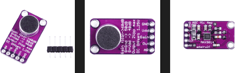
Pin Out
The MAX9814 has five pins.
| Pin | Description |
|---|---|
| GND | Ground |
| Vdd | Module Power Supply (2.7-5.5VDC) |
| Gain | Adjusting maximum module output |
| Out | Analog output |
| AR | Adjusting Module Accuracy |
Accuracy and Gain Adjustments
| Pin | Disconnected | VCC | GND |
|---|---|---|---|
| Gain | 60dB | 50dB | 40dB |
| AR | 1:4000 | 1:2000 | 1:500 |
How it Works
The MAX9814 module has a microphone that converts sound signal into electrical signal. The signal is then amplified and the module outputs this as analog signal from 0-1023. The higher the value, the higher the intensity of sound.
Project - Arduino Sound Intensity Monitor
This project will demonstrate how the ultraviolet light intensity from a source is detected and converted to an analog signal and this value is displayed in the serial monitor.
Components
- Arduino Uno Board (1 pc.)
- Microphone Amplifier Module with AGC and Low-Noise Bias – MAX9814 (1 pc.)
- Jumper Wires
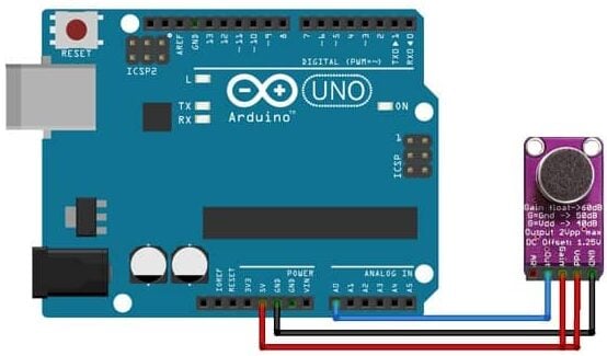
Wiring Diagram
The MAX9814 module pins are connected to the Arduino Uno board as follows:
| Module Pin | UNO Board Pin |
|---|---|
| GND | Ground |
| Vdd | 5V |
| Gain | 5V |
| Out | A0 |
| AR | No Connection |
Code
					//initialize variable
int sensorValue;
void setup() {
  // initialize serial communication at 9600 baudrate
  Serial.begin(9600);
}
void loop() {
  // get the analog value
  sensorValue = analogRead(A0);
  // display the analog value to serial monitor
  Serial.println(sensorValue);
  }
Project Test
Wire the components to the Arduino as demonstrated in the wiring diagram. Connect the Arduino to a PC and upload the program. Open the serial monitor in the Arduino IDE and the intensity of the sound received by the microphone will be displayed.


