Introduction
This tutorial details the TB6612FNG module, how it functions and the method of building a simple project using the TB6612FNG module and an Arduino.
TB6612FNG Dual DC Stepper Motor Driver Module
The TB6612FNG module has a built-in microphone and an amplifier circuit. The module can be used with a motor of up to 2 DC to control its speed and rotation.
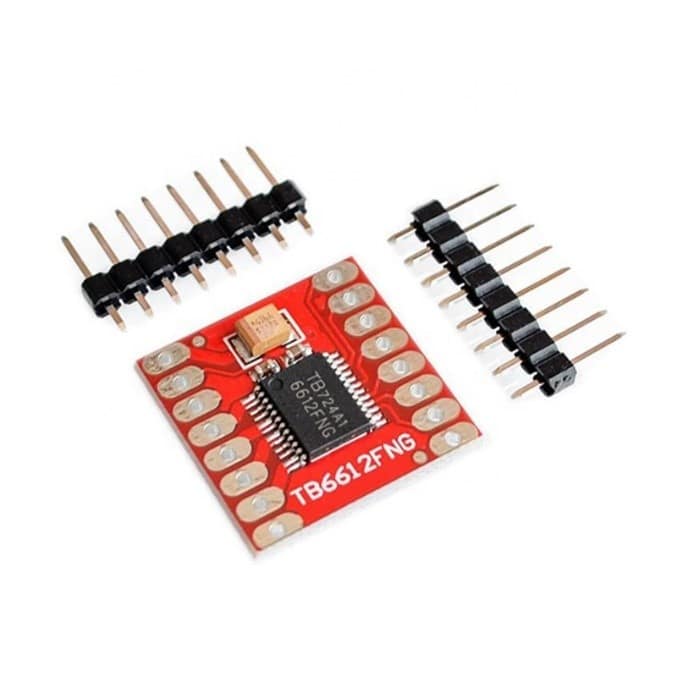
Pin Out
The TB6612FNG has 16 pins.
| Pin | Description |
|---|---|
| VM | Motor Voltage |
| VCC | Logic Voltage |
| GND | Ground |
| AO1 & AO2 | Motor A Rotation Control Output |
| BO1 & BO2 | Motor B Rotation Control Output |
| PWMA | Motor A Speed Control Input |
| AI1 & AI2 | Motor A Rotation Control Input |
| STBY | Standby |
| BI1 & BI2 | Motor B Rotation Control Input |
| PWMB | Motor A Speed Control Input |
How it Works
The TB6612FNG module takes digital and analog signal for rotation and speed control, respectively. The module can control a motor up to 2 DC with just one module and a microcontroller.
Project - Arduino Dual DC Motor Control
This project will demonstrate how the TB6612FNG module can control two DC motors.
Materials
- Arduino Uno Board (1 pc.)
- TB6612FNG Dual Dc Stepper Motor Driver Module (1 pc.)
- DC Motor (2pcs.)
- External Power Supply (Batteries)
- Jumper Wires
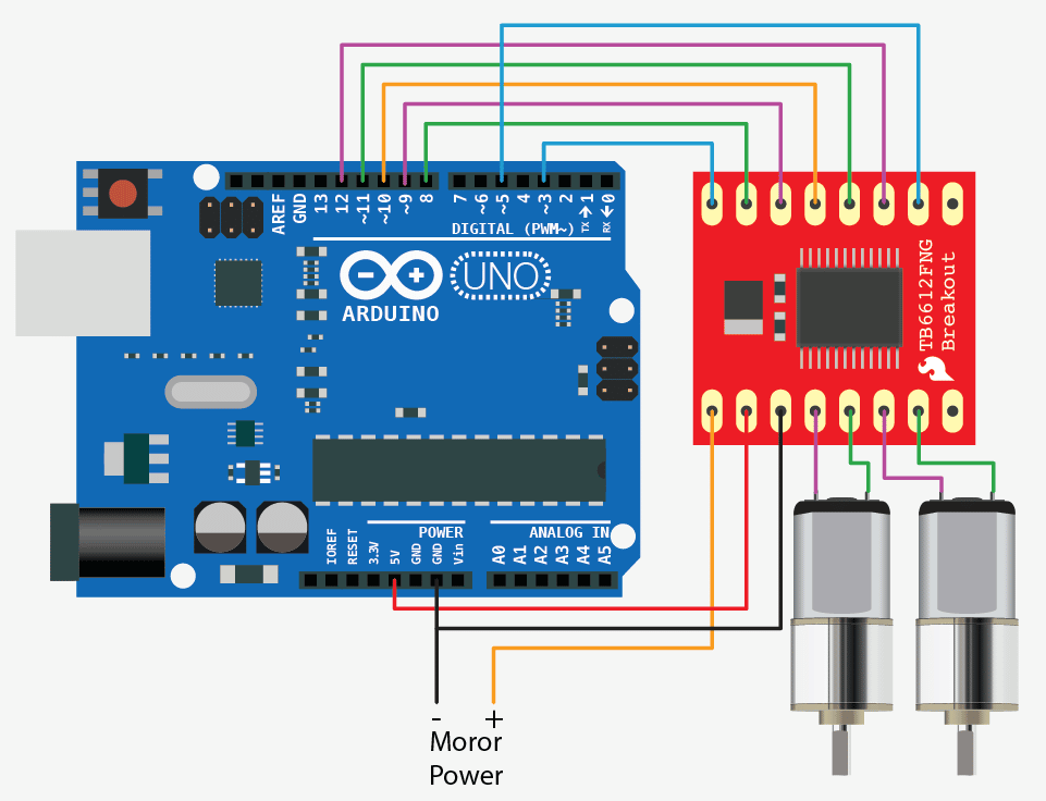
Wiring Diagram
The TB6612FNG module pins are connected to the Arduino Uno board and DC motors as follows:
| Module Pin | UNO Board/Motor/Battery |
|---|---|
| VM | Battery + |
| VCC | 5V |
| GND | Battery - |
| AI1 | 9 |
| AI2 | 8 |
| PWMA | 3 |
| BI1 | 11 |
| BI2 | 12 |
| PWMB | 5 |
| STBY | 10 |
| GND | Ground |
| AO1 | Motor A- |
| AO2 | Motor A+ |
| BO1 | Motor B- |
| BO2 | Motor B+ |
Code
					//motor A connected between A01 and A02
//motor B connected between B01 and B02
int STBY = 10; //standby
//Motor A
int PWMA = 3; //Speed control
int AIN1 = 9; //Direction
int AIN2 = 8; //Direction
//Motor B
int PWMB = 5; //Speed control
int BIN1 = 11; //Direction
int BIN2 = 12; //Direction
void setup(){
pinMode(STBY, OUTPUT);
pinMode(PWMA, OUTPUT);
pinMode(AIN1, OUTPUT);
pinMode(AIN2, OUTPUT);
pinMode(PWMB, OUTPUT);
pinMode(BIN1, OUTPUT);
pinMode(BIN2, OUTPUT);
}
void loop(){
  //disable standby to make the motors run
  digitalWrite(STBY,HIGH);
  //set motor A and motor B speed, 0-255 255 being the fastest
  analogWrite(PWMA,255);
  analogWrite(PWMB,127);
  //set motor A direction
  digitalWrite(AIN1,LOW);
  digitalWrite(AIN1,HIGH);
  //set motor B direction
  digitalWrite(BIN1,LOW);
  digitalWrite(BIN1,HIGH);
  delay(50000);//the two motors will spin in opposite direction for 5 seconds. motor A spins at full speed while motor b spins at half speed
  //enable standby to make the motors stop spinning
  digitalWrite(STBY,LOW);
  delay(1000); //the two motors will stop spinning for 1 second

}
Project Test
Wire the components to the Arduino as demonstrated in the wiring diagram. Connect the Arduino to a PC and upload the program. Both motors will spin in different directions for 5 seconds; motor A will spin at full speed while motor B will spin at half speed. Then, both motors will stop for 1 second before spinning again.