Introduction
Light Dependent Resistor or LDR module is an input module that sends signals (digital or analog) to your Arduino depending on the intensity of light it receives. The sensor has a potentiometer knob that can adjust to change the sensitivity.
The LDR LM393 Module
Specifications
- Operating Voltage: 5 VDC
- Current Draw: 15 mA
- Integrated LM393 Voltage Comparator
- Dimension: 40mm x 16mm x 7mm (L x W x H)
Components
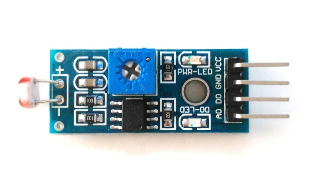
- Light Dependent Resistor (LDR) – A component that changes the value of its resistance depending on the light intensity it receives.
- Power Light (PWR-LED) – Turns on when the device is powered on.
- Indicator Light (DO-LED) – Turns on and off depending on the intensity of light the sensor receives. The sensitivity adjuster enables sensitivity to be adjusted. The module turns on when a high digital signal is sent and off when the digital signal is low.
- Sensitivity adjuster – Adjusts the sensitivity towards the light intensity determining when the device will send a high or low signal.
- VCC – Connected to 3.3 V or 5 V supply.
- GND – Connected to the ground pin.
- DO – Connected to the digital pin of your selection in your Arduino. It outputs high or low signals depending on the light intensity which is based on the sensitivity set on the sensitivity adjuster.
- AO – Connected to the analog pin of your selection in your Arduino. It outputs analog signal depending on the light intensity the LDR received.
Project - Automatic Light Switch
The LDR module can be used to sense the surrounding light of a room. When the detected light intensity is low, the module will automatically turn on the light bulb. When the detected light intensity is sufficient, the light bulb will turn off.
Components
- Arduino Uno
- Light Dependent Resistor Module
- Relay Module
- Light Bulb
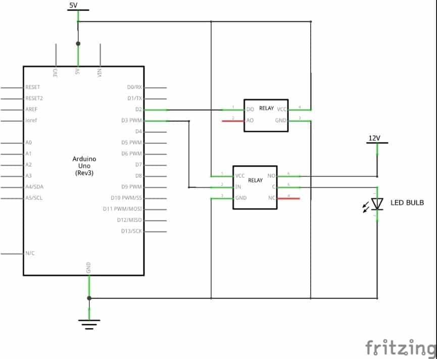
Schematic Diagram
Code
					#define ldrPin 2
#define relayPin 3

void setup()
{
  pinMode(ldrPin,INPUT);
  pinMode(relayPin,OUTPUT);
  digitalWrite(relayPin,HIGH);
}

void loop()
{
  if(digitalRead(ldrPin) == HIGH)
  {
    digitalWrite(relayPin,HIGH);
  }
  else
  {
    digitalWrite(relayPin,LOW);
  }
}
Code Explanation
#define ldrPin 2 – The LDR module is connected to arduino pin 2
#define relayPin 3 – The relay module is connected to arduino pin 3
void setup() {} – Everything inside the {} of this function runs only once on start up.
pinMode(ldrPin,INPUT); – The LDR pin is set as input which sends the signal to the arduino
pinMode(relayPin,OUTPUT); – The relay pin is set as output. The arduino will send the signal to the relay to turn the bulb on and off.
digitalWrite(relayPin,HIGH); – In this connection setup, sending a digital high signal on the relay module will turn off the light bulb.
void loop() {} – Everything inside the {} of this function runs repeatedly on loop from top to bottom.
if(digitalRead(ldrPin) == HIGH) { digitalWrite(relayPin,HIGH); } – This is the first condition on the loop. If the arduino receives a high signal from the LDR module (meaning that there is high intensity of light), the arduino will perform the line of code inside the {} which is digitalWrite(relayPin,HIGH). This will result in the light turning off.
else {digitalWrite(relayPin,LOW);} – This means that the first condition is not true therefore there is low intensity of light in the room and the device will turn on the lights.
Project Test
- Follow the wiring as depicted on the schematic diagram. Please note that an AC bulb or any light bulb can be used as long as the proper power supply for that bulb is utilised.
- For safety precautions, unplug the bulb’s power supply, copy the code and upload it to the Arduino.
- Once the code is uploaded, reconnect the power supply of the bulb.
- Cover the LDR module to check if the bulb will turn on. If the bulb does not turn on, adjust the sensitivity adjuster by turning the potentiometer knob until the bulb illuminates.
- Remove the cover and the light bulb should turn off.