Introduction
This tutorial details the GY-49 module, its functions, and the method to build a simple project using the GY-49 and an Arduino.
The Max44009 Ambient Light Sensor Module - GY-49
The GY-49 module is an ambient light sensor with IIC communication protocol output. The module has a low power ambient light sensor with ultra-wide 22-bit dynamic range from 0.045 lux to 188,000 lux.
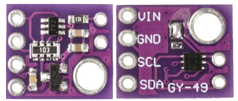
Pin Out
The GY-49 has four pins.
| Pin | Description |
|---|---|
| GND | Ground |
| VIN | Power supply of the module (5VDC) |
| SDA | IIC data pin |
| SCL | IIC clock pin |
How it Works
The GY-49 module uses IIC communication protocol to communicate with the microcontroller.
Project - Arduino Ambient Light Sensor
This project will demonstrate how the GY-49 module detects ambient light and the reading displayed on the serial monitor.
Project - Components Required
- Arduino Uno Board (1 pc.)
- The MAX44009 Ambient Light Sensor Module – GY-49 (1 pc.)
- Jumper Wires
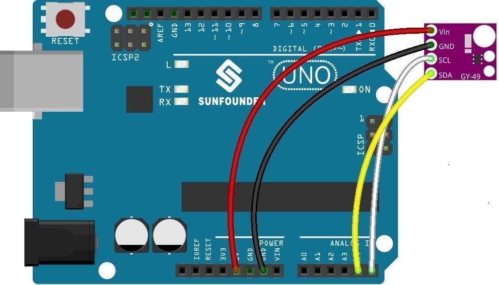
Wiring Diagram
The GY-49 module pins are connected to the Arduino Uno board as follows:
| Module Pin | UNO Board Pin |
|---|---|
| GND | GND |
| VCC | VCC |
| SDA | A4 |
| SCL | A5 |
Code
The library for this module must first be downloaded and can be accessed here; Arduino Library Download
Once the library is installed, the program code can be uploaded.
					#include<Wire.h> //include library
#define Address 0x4A // GY-49 I2C Address is 0x4A(74)
void setup()
{
  //configure gy-49 module
  Wire.begin(); //initialize library
  Serial.begin(9600); //start serial monitor
  Wire.beginTransmission(Address); //start wire iic transmission
  Wire.write(0x02); // Select configuration register
  Wire.write(0x40); // Continuous mode, Integration time = 800 ms
  Wire.endTransmission(); // Stop iic transmission
  delay(300);
}
void loop()
{
  unsigned int data[2];
  Wire.beginTransmission(Address); //start wire iic transmission
  Wire.write(0x03); // Select data register
  Wire.endTransmission(); // Stop iic transmission
  Wire.requestFrom(Address, 2); // Request 2 bytes of data
  // Read 2 bytes of data
  // luminance msb, luminance lsb
  if (Wire.available() == 2)
  {
    data[0] = Wire.read();
    data[1] = Wire.read();
  }
  // Convert the data to lux
  int exponent = (data[0] & 0xF0) >> 4;
  int mantissa = ((data[0] & 0x0F) << 4) | (data[1] & 0x0F);
  float luminance = pow(2, exponent) * mantissa * 0.045;
  // Output data to serial monitor
  Serial.print("Ambient Light Luminance :");
  Serial.print(luminance);
  Serial.println(" lux");
  delay(300);
}
Project Test
Wire the components to the Arduino as demonstrated in the wiring diagram. Connect the Arduino to a PC and upload the program. Open the Serial Monitor in the Arduino IDE and the ambient light luminance that the module detects will be displayed.


