Introduction
This tutorial details the GY-33 module, its functions, and the method to build a simple project using the GY-33 and an Arduino.
The GY-33 Colour Recognition Sensor Module – TCS34725
The GY-33 module can provide digital returns of RGB (Red Green Blue) and clear light sensing values. The module has high sensitivity, wide dynamic range and IR Blocking filter that assures that the output is proper and correct even under different lighting conditions.
Figure 1 shows the image of the GY-33;
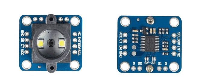
Pin Out
The GY-33 has nine pins.
| Pin | Description |
|---|---|
| GND | Ground |
| DR | Serial Port IIC/UART |
| VCC | Power Supply (3-5VDC) |
| NC | No Connection |
| INT | Colour Chip Break Off Pin |
| SDA | Colour Chip IIC Data Pin |
| SCL | Colour Chip IIC Clock Pin |
| S0 | Serial/IIC Mode Select |
| S1 | Sensor Chip Mode Select |
How it Works
The GY-33 has a built-in LED and RGB recognition sensor. The light reflects from the object into the module sensor. Light that penetrates the IR blocking filter is recognised by its RGB ratio. These values are then converted into analog signals and sent to the microcontroller with IIC communication protocol.
Project - Arduino Colour Recognition Monitor
This project will demonstrate how a GY-33 module shows the colour detected in the serial monitor.
Components
- Arduino Uno Board (1 pc.)
- GY-33 Colour Recognition Sensor Module – TCS34725 (1 pc.)
- Jumper Wires
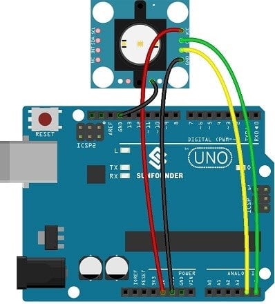
Wiring Diagram
The GY-33 module pins are connected to the Arduino Uno board as follows:
| Module Pin | UNO Board Pin |
|---|---|
| VCC | 5V |
| CT | A5 |
| DR | A4 |
| GND | GND |
| SO | GND |
Code
The library for this module must first be downloaded and can be accessed here; I2c Master Library
Once the library is installed, the program code can be uploaded.
					#include <i2cmaster.h>
#define uint16_t unsigned int
typedef struct
{
    uint16_t Red;
    uint16_t Green;
    uint16_t Blue;
    uint16_t Clear;
} RGB;
unsigned char Re_buf;
unsigned char sign=0;
RGB rgb;
uint16_t CT=0,Lux=0;
byte color=0,rgb_data[3]={0};
void setup() {
       Serial.begin(115200);
       i2c_init();
        delay(1);
}
void loop() {
  unsigned char data[9]={0};
 if(!sign)
 {
   iic_read(0x00,data,8);
   rgb.Red=(data[0]<<8)|data[1];
   rgb.Green=(data[2]<<8)|data[3];
   rgb.Blue=(data[4]<<8)|data[5];
   rgb.Clear=(data[6]<<8)|data[7];
    Serial.print("Red: ");
   Serial.print(rgb.Red);
   Serial.print(",Green: ");
   Serial.print( rgb.Green);
    Serial.print(",Blue");
    Serial.print( rgb.Blue);
     Serial.print(",Clear");
    Serial.println(rgb.Clear);
    iic_read(0x08,data,4);
     Lux=(data[0]<<8)|data[1];
     CT=(data[2]<<8)|data[3];

    Serial.print("CT:");
    Serial.print(CT);
    Serial.print(",Lux:");
    Serial.println( Lux);
     iic_read(0x0c,data,3);
    rgb_data[0]=data[0];
    rgb_data[1]=data[1];
    rgb_data[2]=data[2];
    Serial.print("r:");
    Serial.print( rgb_data[0]);
    Serial.print(",g:");
    Serial.print( rgb_data[1]);
    Serial.print(",b:");
    Serial.println( rgb_data[2]);
     iic_read(0x0f,data,1);
     color=data[0];
     Serial.print(",color:");
    Serial.println( color,HEX);
 }
 if(sign==1)
 {
   iic_read(0x10,&data[8],1);
   i2c_start_wait(0xb4);
    i2c_write(0x10);
    i2c_write(0x31);
   // i2c_write((data[8]|0x01));
    i2c_stop();
    sign=3;
 }
   delay(200);
}
void iic_read(unsigned char add,unsigned char *data,unsigned char len)
{
  i2c_start_wait(0xb4);
   i2c_write(add);
   i2c_start_wait(0xb5);
   while(len-1)
   {
    *data++=i2c_readAck();
    len--;
    }
    *data=i2c_readNak();
    i2c_stop();
}
void serialEvent() {
  while (Serial.available()) {
    Re_buf=(unsigned char)Serial.read();
   if (Re_buf=='a')
       sign=0;
    if (Re_buf=='b')
       sign=1;
      Re_buf=0;
  }
}
Project Test
Wire the components to the Arduino as demonstrated in the wiring diagram. Connect the Arduino to a PC and upload the program. Open the Serial Monitor in the Arduino IDE and the colour of the object in front of the sensor will be displayed based on its RGB ratio. Image editing tools can be used to find the name of the colour. Another method would be to use a search engine such as Google.


