Phipps Electronics

Order within the next 

FREE SHIPPING OVER $199

50,000+ ORDERS

WORLDWIDE SHIPPING

SSL SECURED

Using the Photo Interrupter Module KY-010 with Arduino

Contents

Introduction

In this tutorial, we will learn about the KY-010 module, what is a photo interrupter circuit and we will build a simple project using the KY-010 module with Arduino.

Photo Interrupter Module KY-010

The KY-010 Module will be our main component for this tutorial. This module has a photo interrupter circuit mounted on a breakout board. Figure 1 shows the module as seen in fritzing.

Figure 1: KY-010 Photo Interrupter Module

Pinout

The KY-010 module has three pins.

Component PinArduino Uno board Pin
(-)GND
middle+5V
SSignal

What is a Photo Interrupter Circuit?

A photo interrupter circuit uses an emitter (usally diode) and a detector to sense if an object is between the emitter and the detector. The detector senses the light sent by the emitter and when it doesn’t “see” the light, it pulls the pin S state to LOW.

Project - Arduino KY-010 Circuit

After learning about the KY-010 module and the photo interrupter circuit, it is now time to build a project using the module. Our project will use the KY-010 module to detect if an object passed between the emitter and detector.

Components

For this project, we need the following components:

  • Arduino Uno board (1 pc.)
  • KY-010 Photo Interrupter Module (1 pc.)
  • Jumper wires

Wiring Diagram

Figure 2: Connection Diagram

Figure 2 shows the connection between the Arduino Uno and the KY-010 Photo Interrupter Module.

The KY-010 module pins are connected to the Arduino Uno board as follows:

Component PinArduino Uno board Pin
(-)GND
middle+5V
S7

The Code

Below is the Arduino sketch for our project. I have added comments to explain important parts of the code. Save the code as KY-010.ino and upload it to your Arduino board.

				
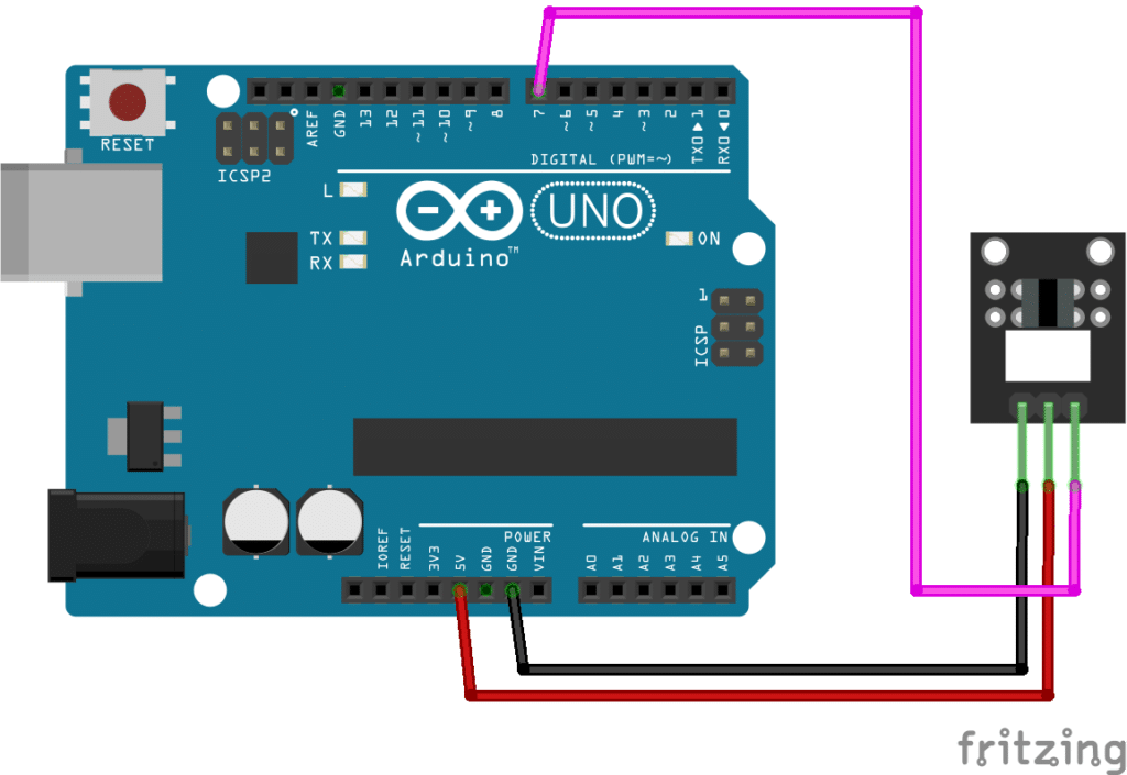
					// Arduino and KY-010 module
void setup()
{
  pinMode(7, INPUT);  // the module is connected to pin 7
  pinMode (13, OUTPUT); // arduino's built-in led is connected to pin 13
}
void loop()
{
  if (digitalRead(7) == LOW) { // check state of pin 7,
                                 // LOW means an objected is detected by the KY-010 module
    digitalWrite(13, HIGH);   // switch On LED
  }
  else digitalWrite(13, LOW); // LED is off when no object is detected
}


Project Test

Apply power to your Arduino Uno board. The built-in LED should light-up when a piece of paper is placed between the KY-010 module’s emitter and detector. Figure 3 shows where to place the paper.

SUBSCRIBE FOR NEW POST ALERTS

Subscribe to be the first to know when we publish a new article!
List Subscriptions(Required)

POPULAR POSTS

Scroll to Top