Want to incorporate your ESP32 WROOMs directly into your projects? Don’t want those bulky devkits in the way? Read along for an ESP32 WROOM series getting started tutorial.
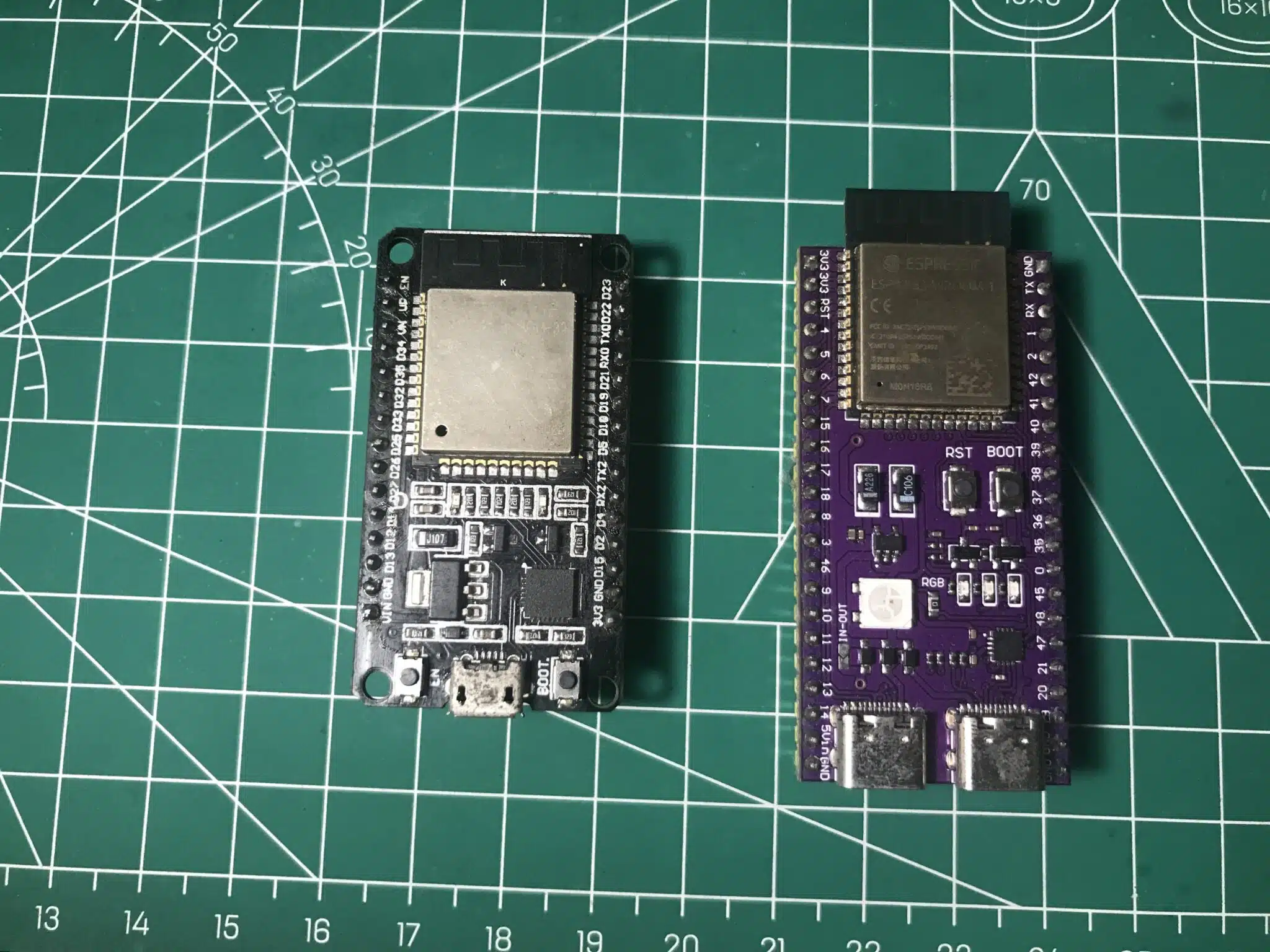
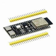
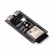
An ESP32 DevKitC-1 and an ESP32-S3 DevKitC-1 side by side.
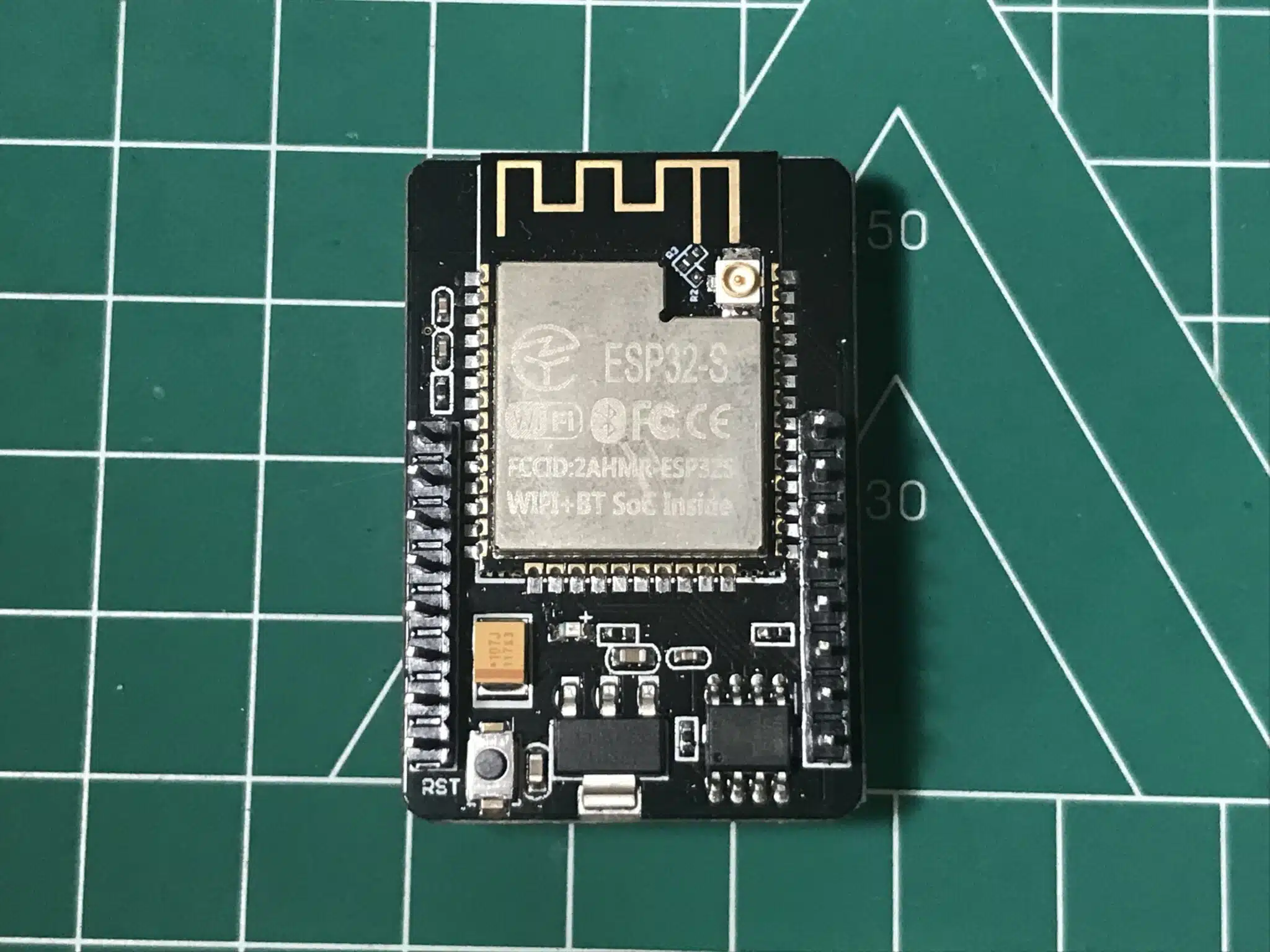
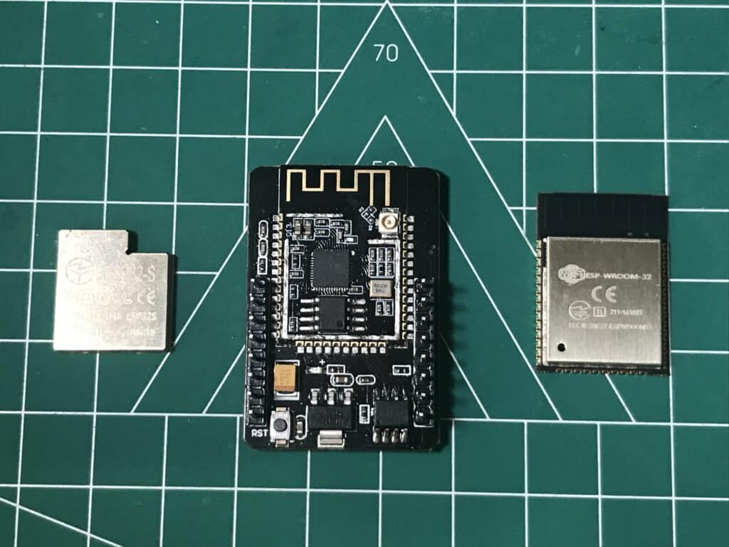
An ESP32 CAM with an embedded ESP32-S (WROOM-like) module.
Introduction
Several ESP32 Devkits have already come out. You’ve probably heard of the DevkitC-1s from Espressif, ESP32 Feather Boards from Adafruit, or the ESP32 boards from Unexpected Maker, to name a few. However, what if you wanted your ESP32 WROOM (or WROVER) module to work stand-alone without any devkit header pins in the way? With this, you’ll save board space as well as component costs.
The ESP32 WROOM Series
The ESP32 is a tiny little chip that can do Wifi, Bluetooth, and other microcontroller-related functions. It’s really just a QFN chip with 48 pins for the ESP32 variant and 56 pins for the ESP32-S3. However, because it will be hard for developers to incorporate this chip into their projects, the IC is set up on a chip on board (COB). One of the standard COBs of Espressif for the ESP32 is the ESP32-WROOM series modules for many of the ESP32 variants.
Examples of popular ESP32 WROOM series are the ESP32-WROOM-32 and ESP32-S3 WROOM-1, to name a few. There was also the WROVER series that is similar to the WROOMs but had built-in PSRAM.
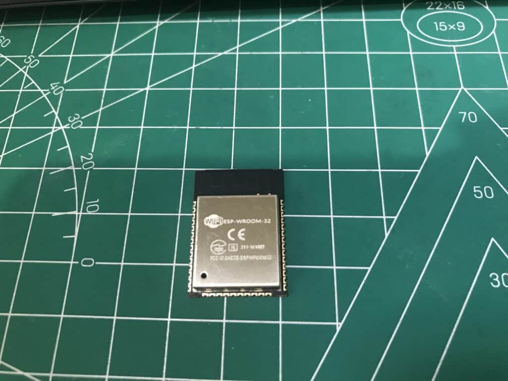
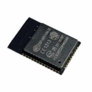
An ESP32 WROOM-32 module. Note that this module is not recommended for new designs.
What's Inside ESP32 WROOMs
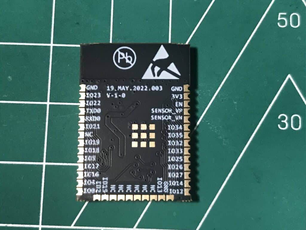
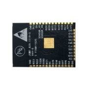
The ESP32 WROOMs simplify working with the ESP32s. You don’t have to worry about complicated crystal, antenna, or additional memory layouts because they are all integrated into the COB. The exposed pads on these modules can readily be used by the user. Below is a sample layout with built-in crystal, flash memory, and antenna circuits.
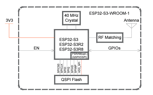
Here is a block diagram of an ESP32-S3-WROOM-1
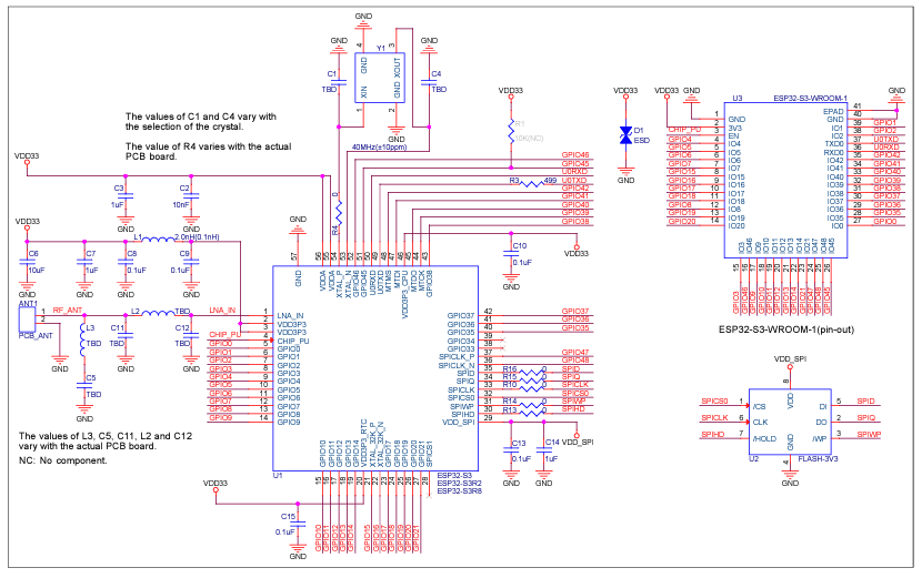
Here is the internal schematic of an ESP32-S3-WROOM
How to Work with ESP32 WROOMs
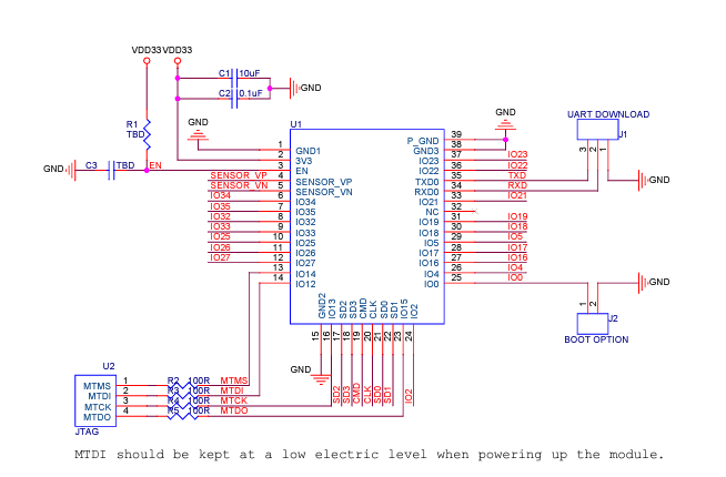
Since these modules already have the essential circuits to function, you only need to power them up and program them correctly before running them on your boards. Below is a typical application circuit of the WROOM (ESP32-S3-WROOM).
To successfully program the ESP32 WROOM you’ll only need to:
Apply power to the 3V3 and GND lines along with added filter capacitors.
Create a Power on Reset Good Circuit (on the EN pad).
Insert a button on the Boot Mode Pin (IO0).
Insert a button on the Reset pin (EN pad).
Insert a terminal for the UART TXD0 and RXD0 programming lines.
Take note of capacitors C1 and C2. They’re needed as power supply filters. C1 is a bulk capacitor that charges up to prepare for large TX bursts during wireless transmissions. C2 is a small filter capacitor at pin 2 (3V3 pad) for the digital supply of the ESP32-S3.
The EN pad is an enable pin for the module. It puts the chip in reset when needed for various situations. Such situations like during initial power-up when the 3.3V supply is not yet stable. Apply a Power On Reset Good Circuit here with an RC value of 10k ohm and 1uF. Also, at the start of programming, you can change the boot mode of the device through this EN pad together with another important pad, IO0 (Boot Option).
Next are the UART pads TX0 and RX0. These pads can readily be used for programming. You’ll be pleased to know you don’t need a separate programmer during your programming sessions since the device can boot up in bootloader mode. You can change boot modes through IO0, as was mentioned before.
A Simplified Circuit Layout
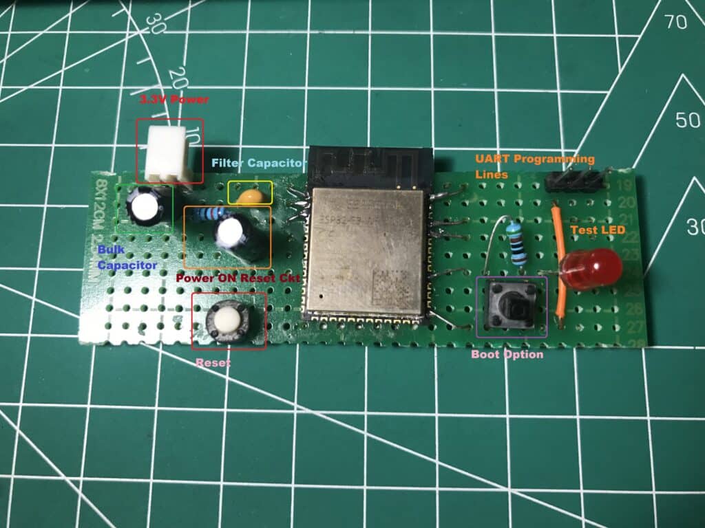
Here is a simplified layout with essential (off-the-shelf) components needed to boot and program your ESP32 device correctly. In the future, you may lay out your own ESP32 WROOM carrier board.
ProgramMER Circuit in Action
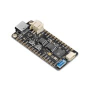
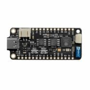
Note that to program your ESP32 boards successfully, you may have to use a USB to UART converter with proper voltage translation. As such, the example used here uses the USB-to-UART converter from an ESP32 CAM carrier board. You may use any USB-to-UART converter with similar characteristics.
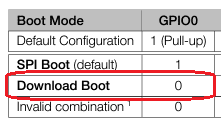
Unlike in a DevKit, you have to manually enter boot mode to be able to program. After power up, press and hold the boot button and then still holding the boot button, press the reset button. Release the buttons afterwards and your ESP32 should enter boot mode. Then click flash device on your PC to program.
Download boot mode is activated through GPIO0 (and another pin, GPIO46, which already has a default value).
Press the reset button after downloading your code to run your program.
Conclusion
It’s easy to get started and program any ESP32 WROOM by just going through this ESP32 WROOM getting started tutorial. All you have to do is follow the basic schematic and circuit layout. You’re now ready to program as many ESP32 WROOMs as you like!