Read this article if you want to learn to write firmware to access your SD cards using the SDIO interface of the STM32 BlackPill.
Introduction
These days, you can save most of your digital media files on the cloud. However, most electronic gadgets still implement digital storage mediums (such as smartphones having an SD card). The reason is that digital storage can access digital media faster than if accessed through the web. Additionally, digital storage media is also available even if you’re offline.
Why Use the SDIO Interface OF Your STM32 BlackPill To Access your SD Card
Your BlackPill has a high-speed SDIO peripheral that can access SD cards much faster than traditional SPI lines. This means you’ll have read and write access speeds fit for mutlimedia applications. Couple this with an ARM-Cortex M4-based microcontroller with advanced features. Such features as I2S, DSP, DMA (Direct Memory Access), FPU (Floating Point Unit), and the like. With the help of secondary storage, such as an SD Card, you can safely store multimedia files that can be accessed later.
How to Connect Your SD Card to the SDIO Port of an STM32F411
SDIO Modes
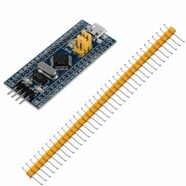
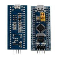
The BlackPill (STM32F411CEU6) has an SDIO port that can be configured in several modes. These modes include 1-bit and 4-bit SD modes or 1-bit, 4-bit, and 8-bit MMC modes. In the following example, 4-bit SD mode is used. This mode should be okay for streaming audio on a Micro SD card.
1-bit SD mode
4-bit SD mode
1-bit MMC mode
4-bit MMC mode
8-bit MMC mode
SDIO Lines
In SDIO mode, there is a CMD line, a Clock line, and several Data lines.
CMD port – Command / Response line associated with the SD card setup phase.
CK port – The bit clock used for Command or Data transfers.
Data Port – 1 – 8 bits of data lines streamed into or out of the SD card.
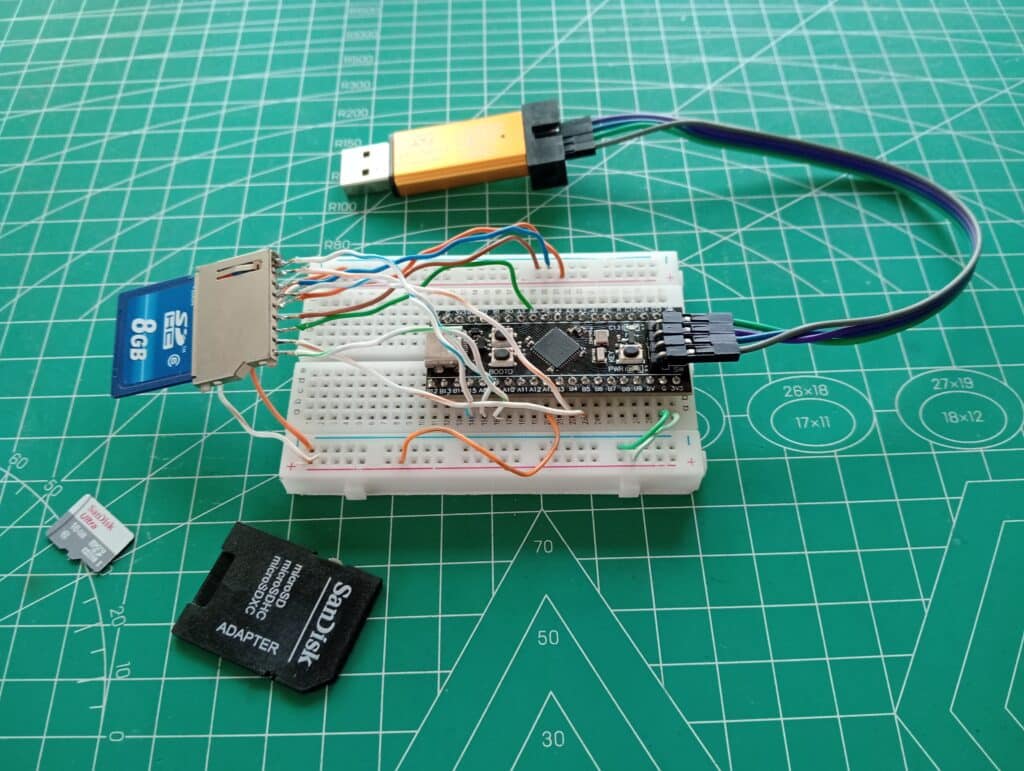
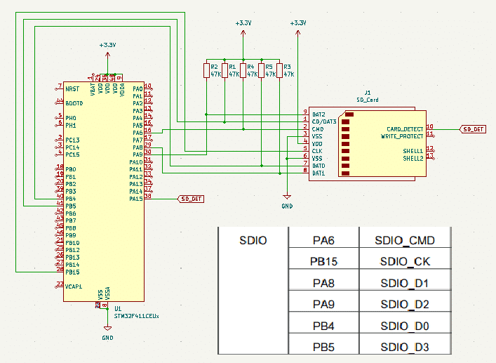
Below, you’ll see a typical connection of an STM32 BlackPill SDIO. Here, pull-up resistors are placed on the Data and CMD lines and their values depend on the line signal integrity intended by the user. However, if you want to save on parts count, you can use the internal pull-up capability of the STM32F4 ports. When using external pull-ups, usually, a value of 10k – 47k is used. Using lower values can mean higher current consumption. You can also wire an SD card detect pin to know if an SD card is inserted into the slot. Note that SD cards work with a 3.3V power supply.
If you’re using I2S, you can use I2S1 so that by default, the pin assignments of SDIO do not interfere with your I2S peripheral.
Using STM32 CubeMX to Setup SDIO
Basic Clocks and Ports
Before going on, you may want to check this STM32 Cube IDE Tutorial. You should be able to setup your clocks, GPIO pins, and an LED indicator.
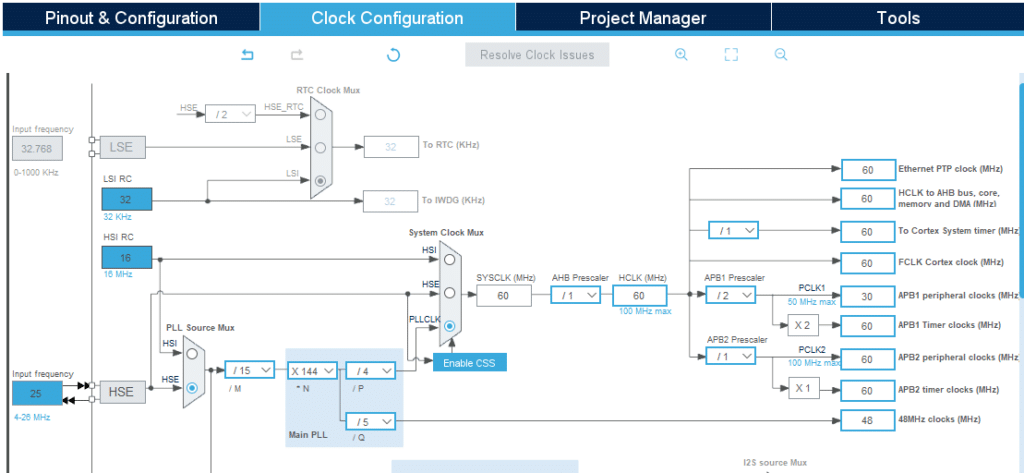
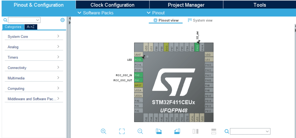
Clock configuration
Note that the SDIO interface uses the PLL clock and it should be close to 48 MHz; the same as what the USB peripheral uses.
An input SD_det pin is used (at PA15) to detect the presence of an SD card. The LED indicator of the Black Pill is assigned to PC13.
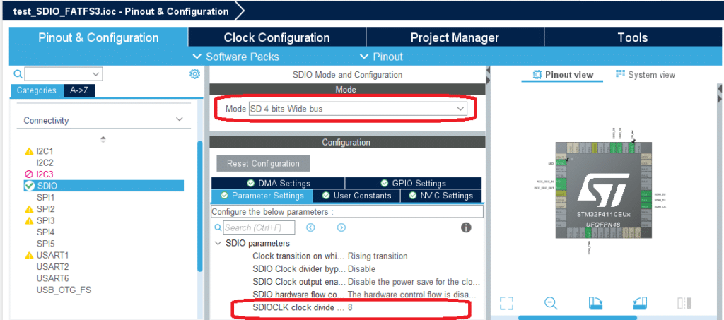
Setting up SDIO
On Connectivity, you should see the SDIO peripheral to set up. Set the Mode to SD 4-bit Wide bus. You can leave the SDIO parameters to their default values. However, for the SDIOCLK clock divider, a value is chosen to match what your SD card can handle. The SDIOCLK can vary between 187 kHz to 24 MHz.
The main equation to get SDIOCLK is given by:
Clock Freq / (clock divide + 2) = SDIOCLK
As an example, a clock divider factor of 8 can be used to achieve an SD card frequency of 4.8 MHz (based on the PLL clock). However, you may have to test your setup on what clock frequency it can handle.
After that, make sure to use DMA requests to your SDIO transmit and receive streams. Also, enable interrupts for your DMAs and the SDIO Global interrupt as these settings are required to successfully run SDIO using CubeMX.
Also, make sure to set up your SDIO GPIO I/O ports according to your pull-up/pull-down resistor setup.
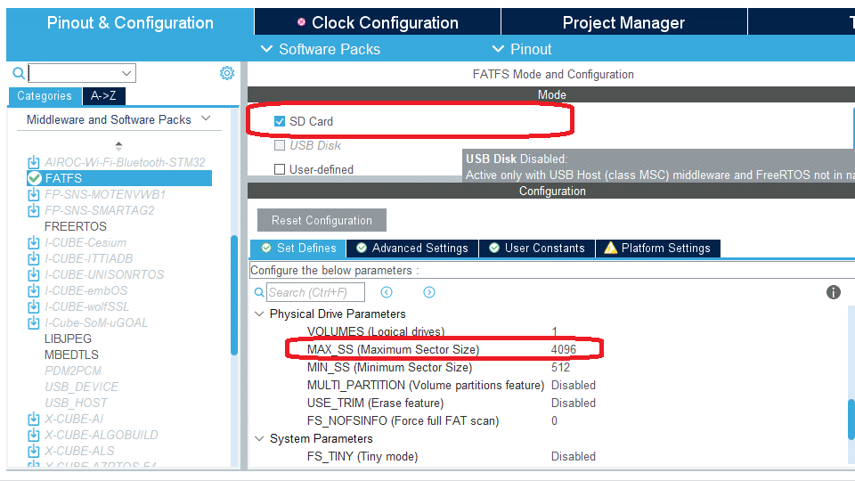
Adding a FAT Filesystem
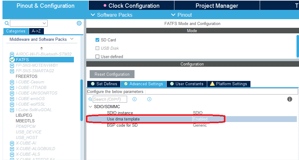
You need a file system to create and access files on your SD card. With this, a FATFS Middleware Stack is added to the code. Go to Middleware and Software Packs and Choose FATFS. In Mode, choose SD Card. Setup the Maximum Sector Size to be 4096 in the Set Defines tab to make your setup flexible in accepting cards.
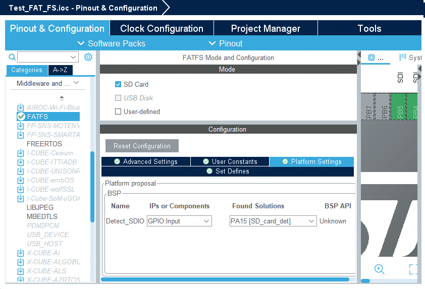
The FATFS stack may need an SD Card detect pin in the code. With this, go to Platform Settings and define your SD card detect pin.
Enable the FATFS to use DMA templates in Advanced Settings.
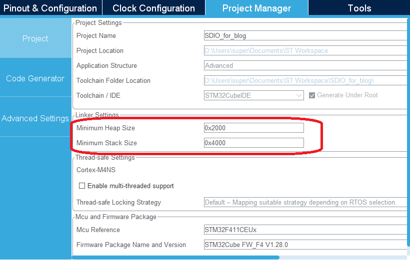
You may increase the heap size if necessary.
Go ahead and Generate your Code.
Create Code to test the SDIO InterfacE
The user should create a custom code to run or test his SD card. The code is composed mainly of FATFS-coupled SDIO functions. The main goal is to create SD card initialization, writing, or reading functions to test your SD card.